


MLC 104 IP Plus • Hardware Setup
Hardware Setup, cont’d
2-4
MLC 104 IP Plus • Hardware Setup
2-5
MLC 104 IP Plus
Right Side Panel
COMM LINK
A B C D E
+V OUT
GROUND
CM
IR IN
SCP
E
C
B
A
SCP communication (IR)
Ground ( )
IRCM, ACM, RCM, CM
+12 VDC
C
B
A
Maximum =
2 SCPs
Per System
Maximum =
4 Control
Modules
(4 module
addresses)
Ground ( )
+12 VDC
Ground ( ) & Drain Wire
E
C
B
A
SCP Communication
Control Module Communication
+12 VDC
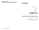
= White
= Black & Drain Wire
= Violet
= Red
IRCM, ACM, RCM, CM
DVD & VCR CONTROL
PLAY NEXT/FWD PAUSE STOP
TUNER
Tx
PREV/REW
ENTER
TITLE MENU
TV/VCR
DVD VCR
SCP 104
IRCM-DV+
CONFIG
DISPLAY
VOLUME
SCP 104
ON
PC
VCR
DVD
OFF
1
2
3
4
200' (61 m) max.
to Last Device
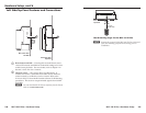
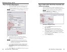
Extron CTLP Cable Color Code:
An MLC 104 IP Plus controller daisy chained to a
SCP 104 remote panel
N
The maximum distance allowed between an MLC
controller and a SCP 104 is 200’ (61 m).
c
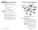
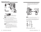
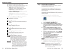
Digital I/O — This port is configurable as a digital input or
digital output and can be used to connect a variety of devices,
such as sensors, switches, LEDs, and relays.
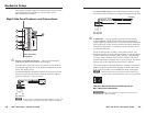
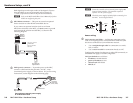
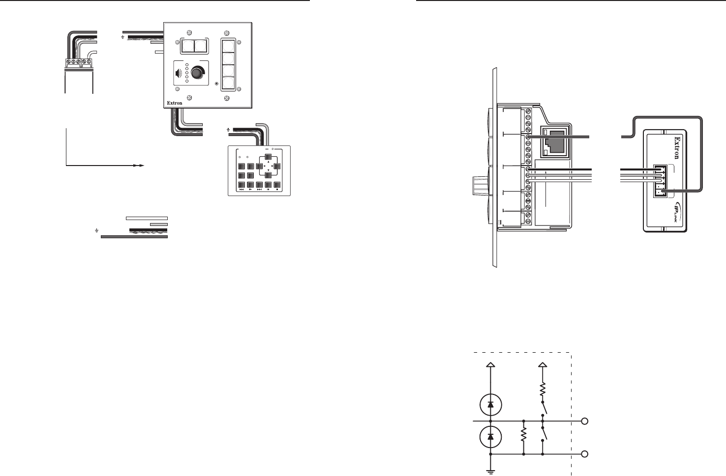
You can connect the Extron IPA T RLY4 to the MLC to enable a
relay function (to raise a projector screen, for example). To use
the IPA T RLY4 with the MLC 104 IP Plus, do the following:
1. Use Global Configurator to set the MLC's digital I/O ports
to output mode.
N
Refer to the MLC 104 IP Plus User's Manual for the
steps to set this port to output.
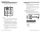
When the MLC's output signal is applied to one of the
IPA T RLY4's relays, that relay’s NO (normally open)
contacts close and its NC (normally closed) contacts open.
2. Connect the MLC's 12 VDC output to the IPA T RLY4's "C"
(common voltage) terminal.
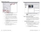
3. Connect the MLC 104 IP Plus' digital I/O wires (from
digital I/O ports 1, 2, and 3) to the IPA T RLY4's inputs
(1, 2, and 3), as shown below. The Extron Comm-Link
(CTL and CTLP) cable is recommended for these
connections.
1
2
3
GROUND
+12V OUT
CM
GROUND
IR OUT
GROUND
SCP
GROUND
Tx
Rx
DISPLAY
RS-232/IR
A B C D E
COMM LINK
LAN
PRESS TAB WITH
TWEEKER TO REMOVE
A B
MLS
RS-232
POWER
12V
DIGITAL
I/O
IR IN
Tx
GROUND
Rx
+12V IN
IPA T RLY4
1 2 3 4 C
INPUTS
MLC 104 IP Plus
Right Side
IPA T RLY4
Front Panel
Relay 1
Relay 2
Relay 3
+12 VDC
N
Refer to the IPA T RLY4 User's Guide for information on
how to wire the IPA T RLY4's relay outputs.
As shown in the illustration below, the digital I/O port is set to
measure two states: on or off; high or low. Its input threshold
voltages are as follows: low is <2.0 V and high is >2.8 V.
24K SW1
2K
+12V +5V
SW2
I/O
GND
An equivalent digital I/O port circuit