


MLC 104 IP Plus • Hardware Setup
Hardware Setup
MLC 104 IP Plus • Hardware Setup
2-32-2
This chapter describes right, left, and front panel features; basic
front panel operation; and how to connect cables to the
MLC 104 IP Plus controller.
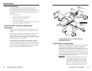
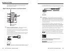
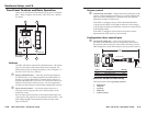
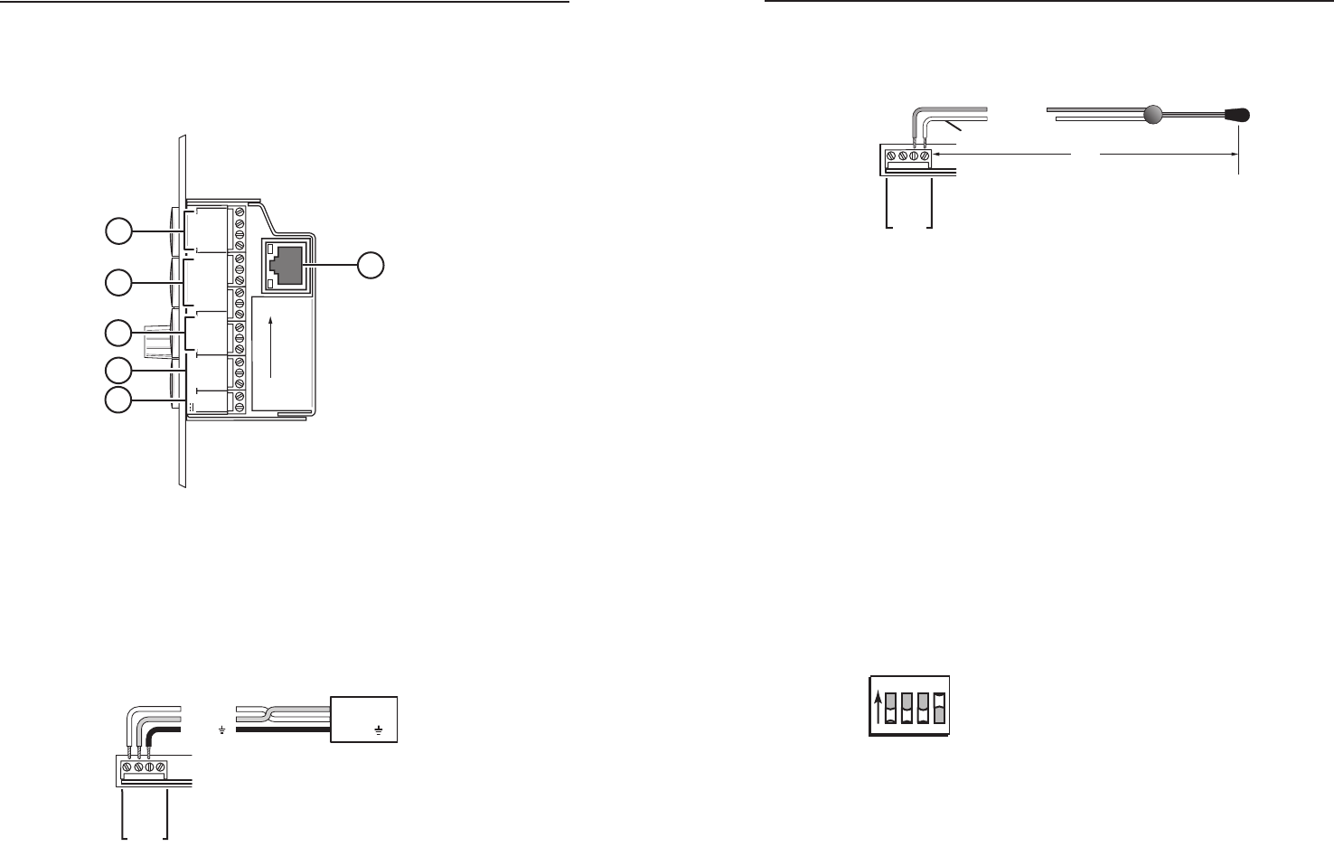
Right Side Panel Features and Connections
2
3
GROUND
1
IR IN
GROUND
IR OUT
CM
SCP
GROUND
GROUND
Tx
Rx
DISPLAY
RS-232/IR
LAN
PRESS TAB WITH
TWEEKER TO REMOVE
A B
MLS PWR
RS-232 12V
DIGITAL
I/O
A B C D E
COMM LINK
+V OUT
GROUND
Tx
Rx
+12V IN
MLC 104 IP Plus
Right Side
4
5
3
2
1
6
a
Display control RS-232 /IR port — This port has dedicated
bidirectional RS-232 and infrared signal output.
From this port, commands sent from a driver or user-defined
command strings (entered via the Global Configurator) can be
sent to the display device.
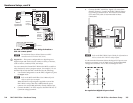
For bidirectional RS-232 communication, the transmit, ground,
and receive pins must be wired at both the controller and the
projector connectors, as shown below.
Projector
Panel
MLC 104 IP Plus
Right Side Panel
DISPLAY
RS-232/IR
GROUND
IR OUT
Tx
Rx
Ground ( )
Receive (Rx)
Transmit (Tx)
Ground ( )
Receive (Rx)
Transmit (Tx)
Bidirectional
N
Each projector or display may require different wiring. For
details, refer to the manual that came with your projector.
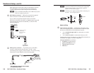
For infrared (IR) output, wire an IR Emitter (2 emitters are the
maximum), as shown below, for a modulated signal and ground.
MLC 104 IP Plus
Right Side Panel
DISPLAY
RS-232/IR
GROUND
IR OUT
Tx
Rx
G = Ground
IR Emitter 1
White Striped Wire
100'
(30.5 m)
S = Signal (IR)
b
COMM Link — You can connect up to four Extron control
modules (IRCMs, ACMs, RCMs, CMs), one Extron IR signal
repeater (IRL 20 or IR Link), and/or two Extron SCP 104 control
pads to this port to allow remote control of the MLC 104 IP Plus
controller or other items. A maximum of seven devices can be
connected to this port.
The SCP 104 replicates the MLC’s front panel controls. The
IR signal repeater can receive IR signals from an optional IR 402
remote control and send them to the controller. Once the MLC
is set up, control modules can be used to control VCRs, DVD
players, tape decks, a projector lift, or screen control. For device
control, refer to the appropriate device’s user’s manual.
The control modules, IR signal repeaters, and SCPs can be daisy
chained, as shown on the following page. Extron Comm-Link
(CTL and CTLP) cable is recommended for these connections.
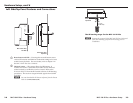
N
When an SCP 104 is connected to an MLC 104 IP Plus,
the SCP's DIP switch #4 must be in the ON (up) position.
1
ON
2 3 4
The SCP's DIP switch #4 set to ON (up) for an
MLC 104 IP Plus connection
W
The SCP 104 must have firmware version 1.01 or
higher installed.