


MLC 104 IP Plus • Hardware Setup
Hardware Setup, cont’d
2-10
MLC 104 IP Plus • Hardware Setup
2-11
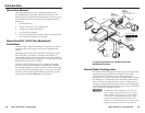
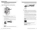
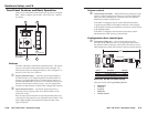
Front Panel Features and Basic Operation
There are several features that must be set up prior to using the
MLC. Refer to chapter 4 in the MLC 104 IP Plus User's Manual
for details.
CONFIG
DISPLAY
VOLUME
MLC 104 IP PLUS
ON
VCR
DVD
PC
OFF
1
2
3
4
MLC 104 IP Plus
Front Panel
4
2
1
3
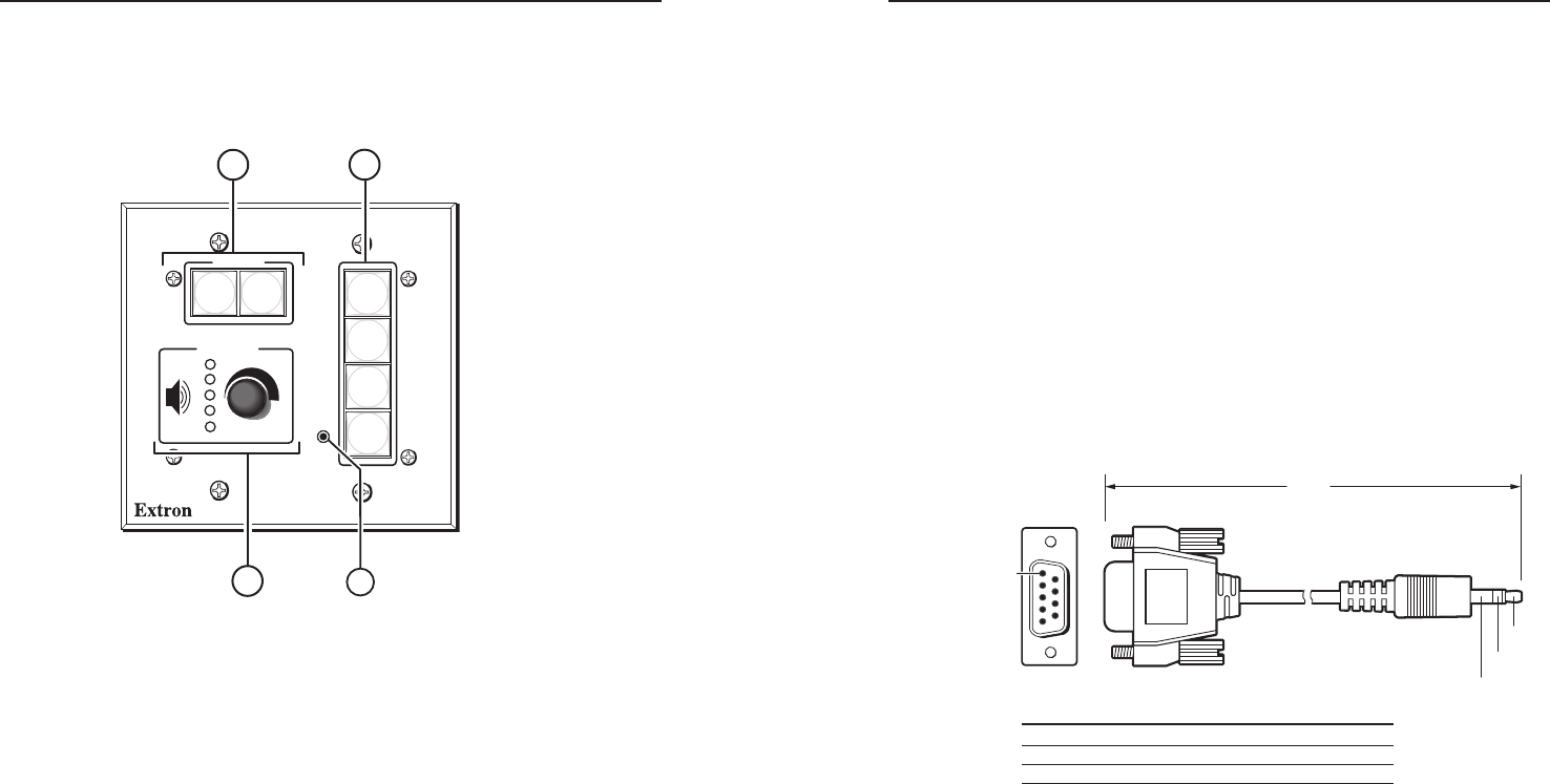
Buttons
The MLC 104 IP Plus controller has backlit buttons. The button
caps are removable so the button labels can be changed. For
instructions on how to change the buttons, refer to chapter 1 of
the MCL 104 IP Plus User's Manual.
a
Display On/Off buttons — After they have been configured
(for instructions, see "Configuring the On and Off buttons" in
chapter 3), press the On button to turn the display device on,
and press the Off button to power it off. Only one of these two
buttons can be selected (active) at once. You can assign other
functions to these buttons via the Global Configurator software.
b
Input selection buttons — By default, these buttons are a
mutually exclusive group (only one of these buttons can be
selected at a time).
Press an input selection button to select the desired audio and
video input to the projector or an optional Extron switcher. The
button lights brighter and remains lit while an audio-video
input is selected.
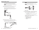
Volume control
c
Volume knob and LEDs — Rotate this knob to adjust the audio
volume. Global Configurator allows you to select whether this
knob will control the projector’s audio levels or the optional
MediaLink switcher’s audio levels.
If the MLC is configured for use with a MediaLink Switcher
or projectors, the MLC’s LEDs light to indicate volume ranges
(with steadily lit LEDs) and minimum/maximum volume limits
(with flashing LEDs).
If the MLC is configured for increment/decrement volume
adjustment, the LEDs scroll up/down briefly.
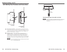
Configuration (host control) port
d
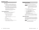
Front panel Config port — This 2.5 mm mini stereo jack
provides an RS-232 connection for configuration and control.
An optional cable for this port is the 9-pin D Female to 2.5 mm
TRS configuration cable, shown below, (Extron part #70-335-01).
6 feet
(1.8 m)
Part #70-335-01
5
1
9
6
Sleeve (Gnd)
Ring
Tip
9-pin D Connection TRS Plug
Pin 2 Computer's RX line Tip
Pin 3 Computer's TX line Ring
Pin 5 Computer's signal ground Sleeve
Pinout for TRS RS-232 cable wiring
This port has the following RS-232 protocol:
• 38400 baud
• 1 stop bit
• no parity
• 8 data bits
• no flow control