


VIPER Technical Manual Detailed hardware description
© 2007 Eurotech Ltd Issue E 18
Detailed hardware description
The following section provides a detailed description of the functions provided by the
VIPER. This information may be required during development after you have started
adding extra peripherals or are starting to use some of the embedded features.
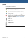
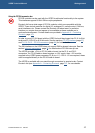
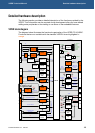
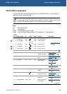
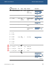
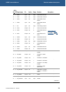
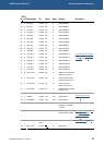
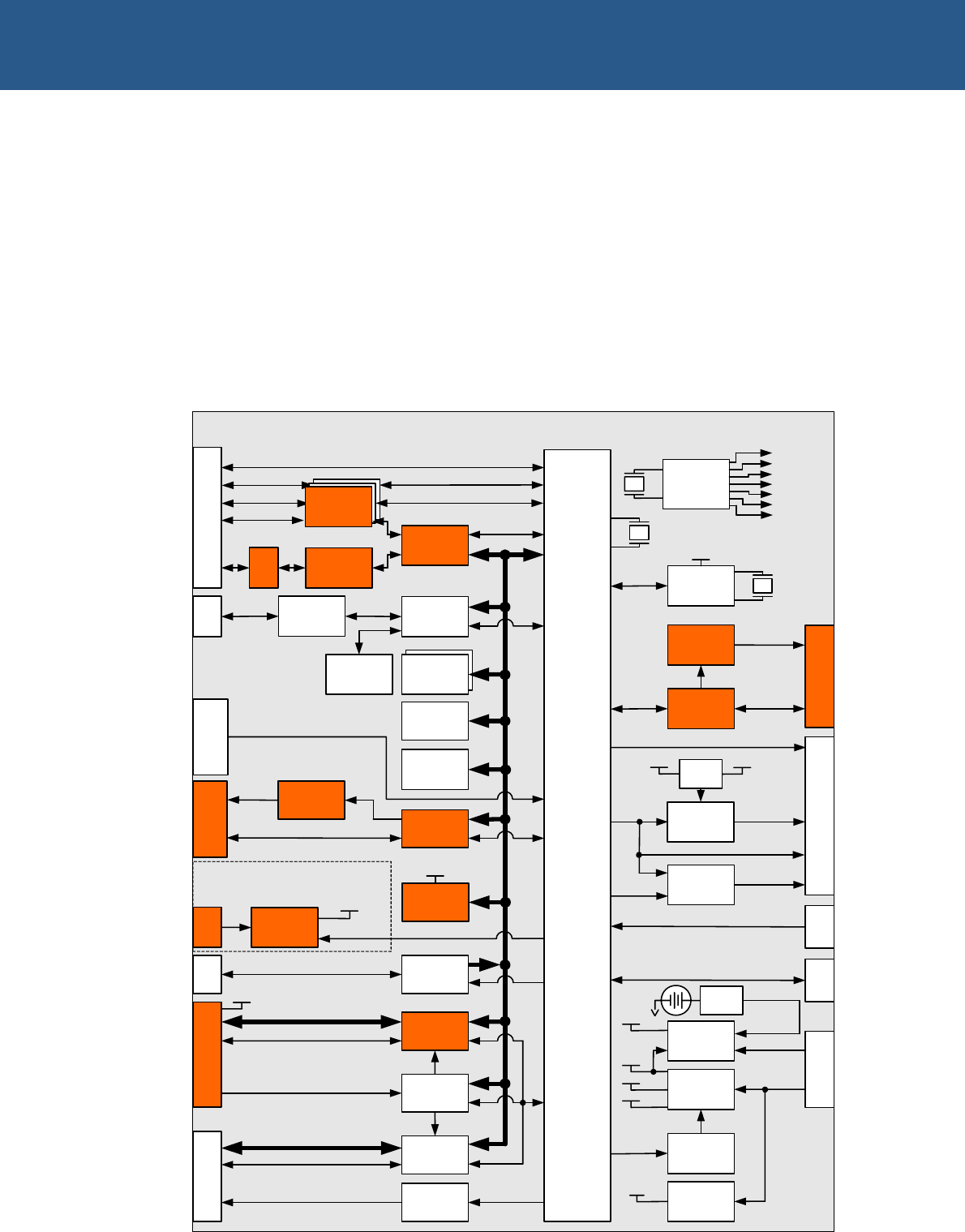
VIPER block diagram
The diagram below illustrates the functional organization of the VIPER PC/104 SBC.
Functions that are not available with the standard VIPER-Lite are highlighted in
orange.
PXA255
1MB
Bootloader
FLASH
16 or 32MB
Silicon
Disk
256kB
SRAM
DUART
PL4
COM 1
TPM
COM 2&3
COM 4
COM5
RS422/485
Transceiver
PL5
CF Power
Switch
USB Power
Switch
Transceivers
CPLD
Transceivers
Address & Data
CF & PC/104 Control Signals
PC/104 Control
PC/104 Address & Data
CF Address & Data
3.3V
CF Control
CF_SWITCH
PL11
&
PL12
LAN91C111
PL1
&
PL2
10/100
baseTX
Serial
EEPROM
Transformer
Transceivers
PL9
IN[0:7] / OUT[0:7]
USB Host
Controller
PL7
USB1 & 2
3.6864MHz
25MHz
Voltage
Monitor
Triple Reg
Reg
1.8V
Micropower
DAC
3.3V
1.06-1.29V
3.3V
5V
EXT_VBAT_IN
3V
Backup
JTAG
14.318MHz
1.8432MHz
6MHz
8MHz
24.576MHz
14.318MHz
Clock
Generation
32.768kHz
RTC
PL6
AMP R+L
LINE IN R+L
LINE OUT R+L
MIC IN
AC'97
Codec
Power
Amp
AC'97
Signals
Dual
MOSFET
PL3
BLKEN &
LCDEN
LCD Signals
Reg
POSBIAS /
NEGBIAS
BLKSAFE &
LCDSAFE
LCDEN
VIPER
Control
Control
5V
Control
Control
PL10
JP3
Control
PL16
Jumper Configuration
64MB
SDRAM
JP1
RS232
Transceivers
I
2
C
PL8
3V
Backup
Optional
3V
Backup
33MHz
PWM1
INT_VBAT_IN
CR2032
JP2
5V
5V
3.3V
LCD_Supply
GPIO[26:27]
3V
Backup
JP4
PL17
USB Client
PC/104 Interrupts