VIPER Technical Manual Detailed hardware description
© 2007 Eurotech Ltd Issue E 44
FPIF-LVDS-TX connectors
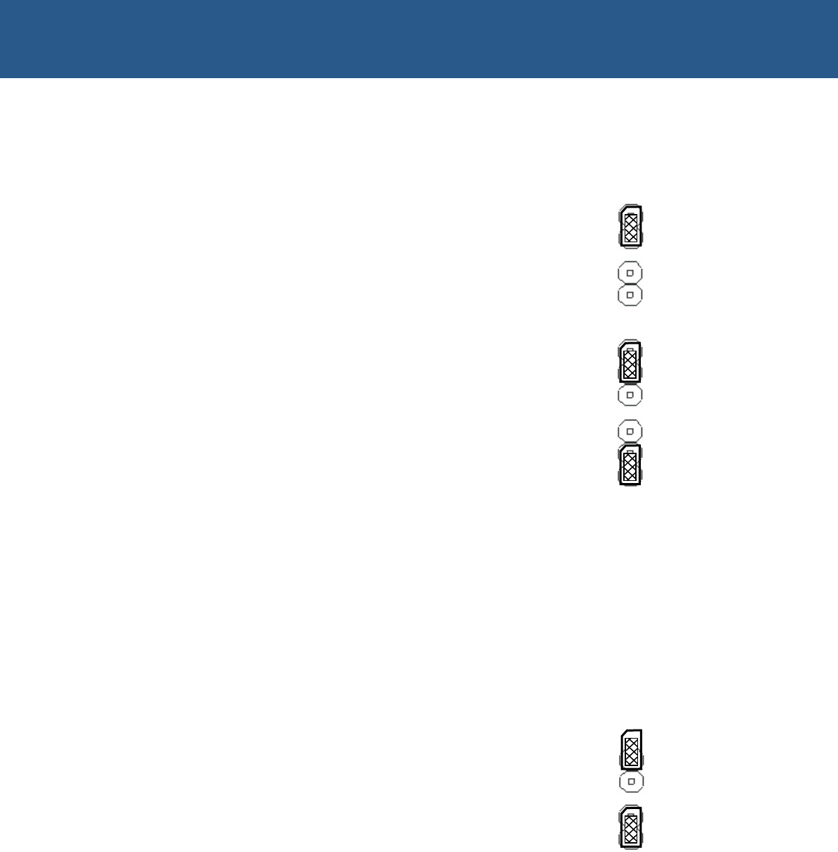
JP1 – TX strobe selection
This link selects the edge of the TX strobe.
If the jumper is fitted (default) then the TX Strobe shall
be on the rising edge. If no jumper is fitted then the TX
Strobe shall be on the falling edge.
JP2 – Cable power selection
This link provides 3.3V or 5V (default) to the J2 and J3
connectors respectively. Please refer to the pin
descriptions of these connectors below for details.
If the FPIF-LVDS-TX is to be connected directly to an
LVDS display then power for the display logic may be
supplied to the display. If using long LVDS cables, it is
advisable to use the CABLE_POWER signal as a
control signal to enable power provided externally.
Backlight power for the display should always be
provided externally.
If the FPIF-LVDS-TX is used in conjunction with the
FPIF-LVDS-RX to extend the VIPER video up to 10
meters, fit the jumper to either position. Ensure that a
jumper is fitted as the CABLE_POWER signal of the
FPIF-LVDS-TX signals to the FPIF-LVDS-RX when to
enable power to the display.
JP3 – MSL selection
If the FPIF-LVDS-TX is to be connected directly to an
LVDS display via the Hirose connector J2, then this link
selects the display’s LVDS receiver input map. Fitting or
not fitting a jumper to JP3 sets J2 pin 20 (MSL) to 3.3V
or GND (default) respectively.
If the MDR connector J3 is used then jumper setting of
JP3 has no effect.
Please consult the manual of your LVDS display for
which setting to use for a National Semiconductor
DS90C383 LVDS transceiver.
Rising edge TX
Strobe (default)
Falling edge TX
Strobe
J2
J3 (default)
Open - GND
(default)
Closed - 3.3V


