VIPER Technical Manual Detailed hardware description
© 2007 Eurotech Ltd Issue E 30
Interrupt assignments
Internal interrupts
For details on the PXA255 interrupt controller and internal peripheral interrupts please
see the PXA255 Developer’s Manual on the Development Kit CD.
External interrupts
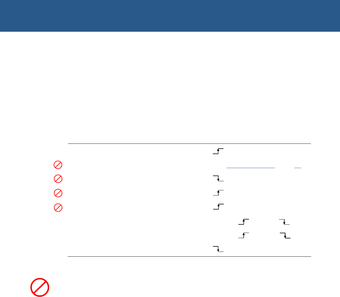
The following table lists the PXA255 signal pins used for generating external interrupts.
PXA255 Pin Peripheral Active
GPIO0 Ethernet
GPIO1 PC/104 interrupt controller See 341HPC/104 interrupts, page 342H30
GPIO2 USB
GPIO3 COM5
GPIO4 COM4
GPIO8 CompactFLASH RDY/nBSY Ready = , Busy =
GPIO14 FLASH (OS) Ready = , Busy =
GPIO32 CompactFLASH card detect
PC/104 interrupts
The PC/104 interrupts are logically OR’ed together so that any interrupt generated on
the PC/104 interface generates an interrupt input on GPIO1.
The PC/104 interrupting source can be identified by reading the PC104I1 & 2 registers
(PC104I2 is not available under Windows CE as all interrupt sources are fully utilized)
located at offset 0x100000 and 0x100004 respectively from CS5 (0x14000000). The
registers indicate the status of the interrupt lines at the time the register is read. The
relevant interrupt has its corresponding bit set to ‘1’. The PXA255 is not designed to
interface to 8-bit peripherals, so only the least significant byte from the word contains
the data.
V
L
VL
VL
VL
VL


