VIPER Technical Manual Detailed hardware description
© 2007 Eurotech Ltd Issue E 33
PC/104 interrupts under Windows CE
Write 0x2 to the ICR Register so that the first PC/104 interrupt source causes the
PXA255 PC/104 interrupt pin GPIO1 to receive a low to high transition. When the first
PC/104 interrupt occurs the Interrupt service routine will start polling through the
PC/104 interrupt sources in the PC104I1 register. The first bit it sees set to a ‘1’, sets a
semaphore to make a program run to service the corresponding interrupt.
Once this program has serviced the interrupt the interrupting source returns its
interrupt output to the inactive state (‘0’) if it hasn’t requested another interrupt whilst
the microprocessor serviced the last interrupt. Once this happens the corresponding bit
in the PC104I1 register shall be automatically cleared. Each PC/104 board requesting
an interrupt shall keep its interrupt in the active state (‘1’) until the interrupt has been
serviced by the microprocessor. When there are no interrupts outstanding the level of
the PC/104 interrupt on GPIO1 shall automatically return to logic ‘0’. If it is still ‘1’ then
there are interrupts outstanding, which would have occurred during the servicing of the
last interrupt.
To capture any interrupts that could have occurred whilst the last interrupt was
serviced, the retrigger interrupt bit in the ICR register is set to ‘1’ to retrigger a low to
high transition on GPIO1 to restart the interrupt polling mechanism if there are any
outstanding interrupts.
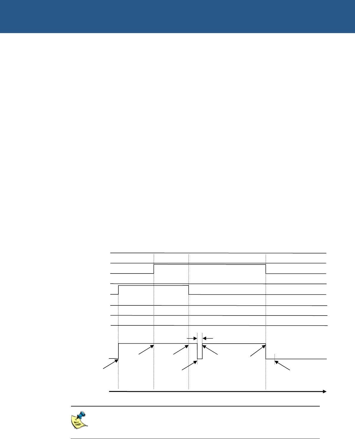
The diagram below explains how the PC/104 interrupt on GPIO1 behaves over time
when the ICR AUTO_CLR bit is set to ‘1’:
PC/104 IRQ9, IRQ14 and IRQ15 are not available under Windows CE as all
interrupt sources are fully utilized; therefore the PC104I2 register is disabled
for Windows CE.
1
s
t
IRQ received
(IRQ service
routine started)
2
n
d
IRQ received
whilst last IRQ is
being serviced
1
s
t
IRQ serviced
(GPIO1 doesn’t
go low)
GPIO1
Level
Time
1.12µs
Set RETRIG bit in ICR
register to ‘1’ to retrigger
interrupt on GPIO1 if there
are any outstanding
interrupts
IRQ service
routine started
2
n
d
IRQ
serviced (GPIO1
goes low
because there
are no
outstanding
interrupts)
Set RETRIG bit in ICR register
to ‘1’ to retrigger interrupt on
GPIO1 if there are any
outstandin
g
interru
p
ts
IRQ3
IRQ4
IRQ6
IRQ12
IRQ7
IRQ5
Highest
Priority
Lowest
Priority
IRQ11
IRQ10


