VIPER Technical Manual Connectors, LEDs and jumpers
© 2007 Eurotech Ltd Issue E 85
Connectors, LEDs and jumpers
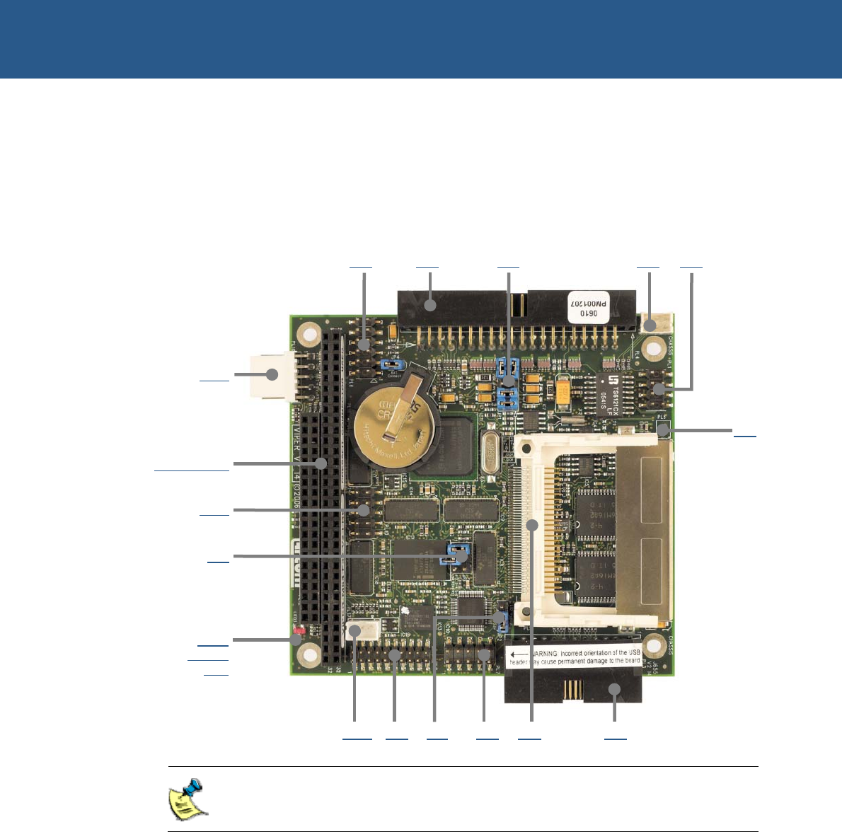
The following diagram shows the location of the connectors, LEDs and jumpers on the
VIPER:
PL6 PL4 JP1 PL2 PL1
PL17 PL9 JP2 PL7 PL5 PL3
The connectors on the following pages are shown in the same orientation as
the picture above, unless otherwise stated.
PL16
PL11 & PL12
PL10
JP3
PL8
Flash
Access
LED


