


ZEUS Technical Manual Detailed hardware description
© 2007 Eurotech Ltd Issue D 18
Detailed hardware description
This section provides a detailed description of the functions provided by the ZEUS.
This information may be required during development after you have started adding
extra peripherals, or are starting to use some of the embedded features.
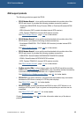
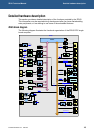
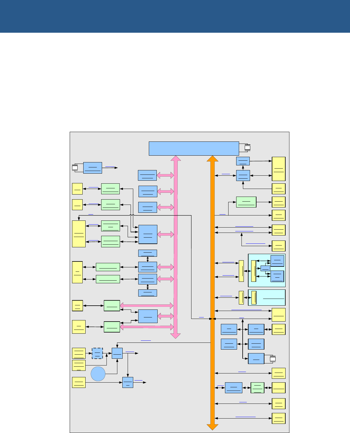
ZEUS block diagram
The following diagram illustrates the functional organization of the ZEUS EPIC single
board computer:
64/128 MB
SDRAM
32/64 MB
FLASH
256 KB
SRAM
QUAD
UART
COMS
Header
COM 4
RS232/422/
485
Transceiver
RS232
Transceiver
COM 3
COM 2
COM 1
RS422/485
Transceiver
CF
Socket
CPLD
Ethernet
Controller
2x
RJ45
Serial
EEPROM
Transformer
2xUSB
Conn.
JTAG
Audio
Header
AC'97
Codec
Power
Amp
LCD
Header
PC/
104
RS232
Transceiver
JTAG
Header
PXA270
M
E
M
O
R
Y
C
O
N
T
R
O
L
L
E
R
B
U
S
PERIPHERALS / GPIO
STUART
FFUART
ZigBee Module
DB9
DB9
I/O
Expander
LCD
USB 1.1 Host
USB 1.1 Host
USB
Header
USB 1.1 Client
GPIO
Header
Quick Capture Camera
Header
I2C
CAN
controller
SPI1
Header
GPIO
User
LEDs
Buffers
Buffers
PSUs
Power
Conn.
10-30V
Power
GPS
Module
GSM/
3G
Module
Daughter Board
BTUART
Header
Socket
PSU
Header
Socket
LVDS
Header
LVDS
Transmitter
CAN
Transc
eiver
TSC
Header
Power
Header
5V
DC/
DC
5V
Reset
IC
Reset
Reset
Button
SDIO
Socket
MMC/SD/SDIO
PM I2C
Battery
AC’97
Ethernet
Controller
Transformer
Serial
EEPROM
ZEUS
I/O
Expander
Config
PROM
RTC
Clock
Generation
Clocks
I2C
Temp
Sensor
I2C