


ZEUS Technical Manual Detailed hardware description
© 2007 Eurotech Ltd Issue D 47
LCD backlight brightness control
GPIO16 of the PXA270 processor is used for backlight brightness control (signal
PWM0 on the J14 connector). The control of the backlight brightness is dependent
upon the type of backlight inverter used with the display. Some inverters have a ‘DIM’
function, which uses a logic level to choose between two levels of intensity. If this is the
case then GPIO16 (Alternative Function 0) is used to set this. Other inverters have an
input suitable for a pulse-width modulated signal or analogue voltage control. In this
case GPIO16 should be configured as PWM0 (Alternative Function 2).
Signal PWM0 is also routed through a low-pass filter on the ZEUS to enable analogue
voltage control of backlight brightness (signal BRT_CTRL on connector J24 – Backlight
power
- see page 92). The voltage range of BRT_CTRL is 0-2.5V.
STN bias voltage
The ZEUS provides a negative and a positive bias voltage for STN type displays
(turned on by the PXA270 GPIO101 pin). The negative and positive bias voltages are
factory set to -22V and +22V respectively. Pin connections for these can be found in
the section J14 – LCD connector
, page 85. Please contact Eurotech Technical Support
(see page 97
) for details of other bias voltages.
Do not exceed 20mA load current.
LVDS interface
There is an optional Low-Voltage Differential Signalling (LVDS) interface available on
the ZEUS. LVDS combines high data rates with low power consumption. The benefits
of LVDS include low-voltage power supply compatibility, low noise generation, high
noise rejection and robust transmission signals.
The National Semiconductor transmitter DS90C363 is used to convert 16-bits of LCD
data signals into three LVDS data streams. A phase-locked transmit clock is
transmitted in parallel with the data streams over a fourth LVDS link. The LVDS signals
are routed to the connector J16. For the connector details see the section J16 – LVDS
connector
, page 86.
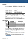
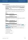
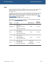
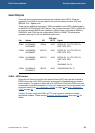
The LVDS transmitter is enabled using the signal LVDS_EN (GPIO21 on PXA270).
Details are shown in the following table:
LVDS_EN
(CPU_GPIO 21)
Selected LVDS function
0 LVDS power down (default)
1 LVDS enable