


ZEUS Technical Manual Detailed hardware description
© 2007 Eurotech Ltd Issue D 42
PC/104 interrupts
The PC/104 interrupts are combined together so that any interrupt generated on the
PC/104 interface generates a single interrupt on the GPIO17 pin of the PXA270
processor.
Reading the PC104_IRQ register located at the address 0x12800000 can identify the
PC/104 interrupting source. The registers indicate the status of the interrupt lines at the
time the register is read. The relevant interrupt has its corresponding bit set to ‘1’. The
PXA270 is not designed to interface to 8-bit peripherals, so only the least significant
byte from the word contains the data.
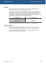
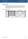
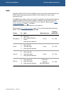
PC/104 interrupt register [REG1]
Byte lane Most significant byte Least significant byte
Bit
15 14 13 12 11 10 9 8 7 6 5 4 3 2 1 0
Field
- - - - - - - - IRQ12IRQ11IRQ10 IRQ7 IRQ6 IRQ5 IRQ4 IRQ3
Reset
X X X X X X X X 0 0 0 0 0 0 0 0
R/W
- - - - - - - -
R/W
Address 0x12800000
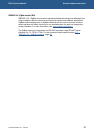
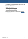
Once the PXA270 microprocessor has serviced a PC/104 interrupt, the corresponding
bit in the PC104_IRQ register has to be cleared by writing a ‘1’ to it. Clearing the
corresponding bit in the PC104_IRQ register will bring GPIO17 level to logic ‘0’ and
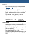
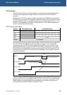
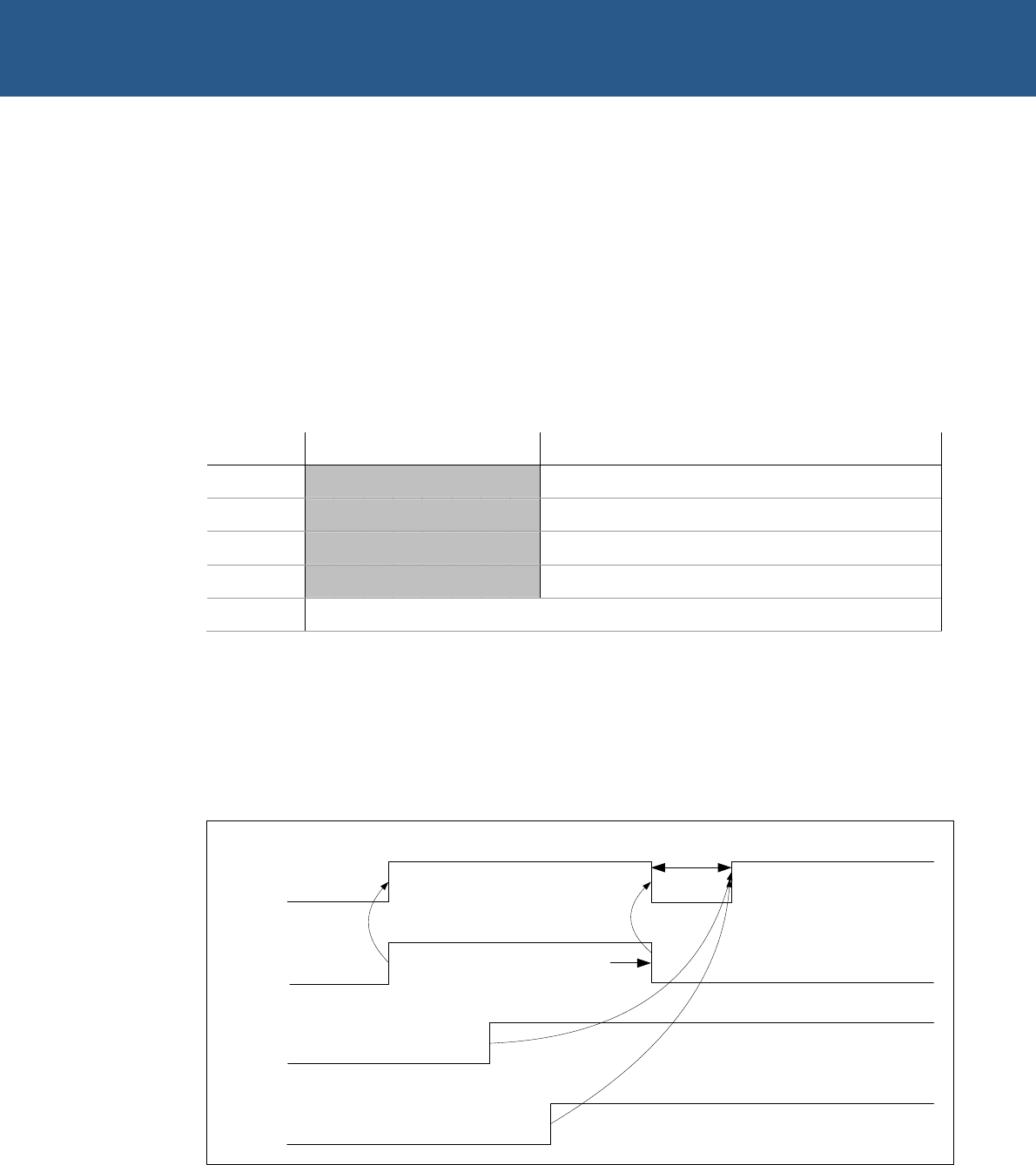
make the interrupt logic ready for the next PC104 interrupt. When one or more other
PC104 IRQs are asserted while the driver is processing PC104 IRQ, the new PC/104
IRQ source has to wait for the current IRQ to be processed. This situation is shown in
the following diagram:
GPIO17
Delay:
250-375ns
PC104_IRQ3
PC104_IRQ6
PC104_IRQ4
Driver clears IRQ3 at source
and in PC104_IRQ register
Driver processing IRQ4
due to priority over IRQ6
Driver processing IRQ3
There is a delay of 250-375ns between the de-assertion of the GPIO17 IRQ signal and
its new assertion due to the pending PC104 interrupt. This delay is introduced into the
ZEUS hardware implementation to accommodate for the minimum inactive time of
GPIO signals required by a PXA270 processor (154ns).