


ZEUS Technical Manual Detailed hardware description
© 2007 Eurotech Ltd Issue D 48
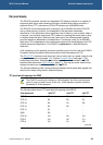
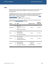
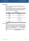
The LVDS transmitter can be programmed for rising edge strobe or falling edge strobe
operation through a signal LVDS_FES# (Expander 2 – GPIO1, I2C address 0x22).
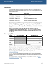
Details are shown in the following table:
LVDS_FES#
(EXP2_GPIO1)
Selected LVDS function
0 Falling edge strobe
1 Rising edge strobe (default)
Connector J24 should be used to supply the power and brightness control for the
backlight inverter when the LVDS interface is used. See the section J24 – Backlight
power
, page 92, for details.