


2-7CrossPoint 300 Matrix Switchers • Installation
Sync termination switches
7
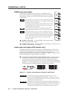
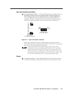
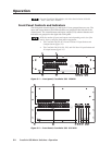
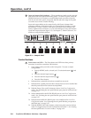
Sync termination switches — The CrossPoint 300 matrix switchers have sync
termination switches on the rear panel for inputs 1 through 4 (figure 2-7).
The switches provide a way to condition non-TTL sync levels greater than
5 Vp-p, enabling the sync to be properly passed from input to selected
output(s). The matrix switchers have two sets of sync termination switches;
one for horizontal or combined sync and a second set for vertical sync.
CrossPoint 300
8
16, 168, 1212, and 1616
CrossPoint 300
84, 88, 124, and 128
H SYNC V SYNC
V
V
15
16
15
16
Figure 2-7 — Sync termination switches
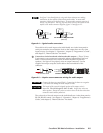
Each switch provides the option of selecting either 510 ohms or 75 ohms.
The 75 ohms position is required only for an input with non-TTL sync, greater
than 5 Vp-p. The normal position is 510 ohms.
An input that produces an out-of-sync display, a display that is rolling
vertically and/or tearing horizontally, could indicate a non-TTL sync input.
A device that is known to output non-TTL sync levels (greater than 5 Vp-p)
should be connected to one of the inputs with sync termination switches, and
the switches for that input should be set to the 75 ohm position. If you are not
sure, check the specifications in the user’s manual for the input device.
Power
8
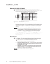
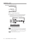
AC power connector — Plug a standard IEC power cord into this connector
to connect the switcher to a 100 VAC to 240 VAC, 50 or 60 Hz power source.