


2-3Matrix 3200/6400 Series • Installation
The following restrictions apply to installing BMEs:
• One BME must be assigned as BME #0.
• BME #0 cannot be a Sync module.
• Address assignments must not skip numbers.
• Address assignments of 0 - 5 are accepted, BMEs w/address 6-9 are ignored.
• A system is limited to one audio module.
• A system may NOT include both Wideband video and Low Resolution video
modules.
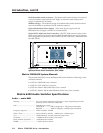
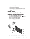
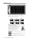
2. Setting BME Addresses
Each BME must be set to a unique address of 0 - 5 using a pushbutton switch
located on the rear panel (see Figure 2-2.B, Item 1). BME #0 will be the Main
Controller and may be any module except the Sync module.
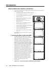
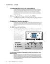
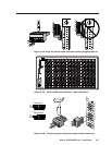
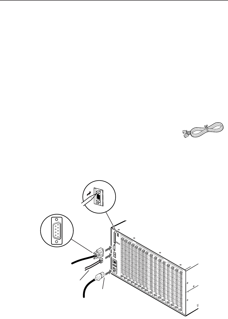
3. Connecting the BME COMM interconnecting cable(s)
If there is more than one BME, the BME COMM connectors
must all be connected together in daisy chain fashion using
Extron supplied RJ-11 telephone cable (Figure 2-2.A). The
chain begins at the BME COMM OUT connector of BME #0
(See Item 2 in Figure 2-2.B) and connects to the BME
COMM IN connector of the closest BME, that BME’s BME
COMM OUT connector is then connected to the next
closest BME if necessary. Repeat this process until all BMEs are connected (No BME
will have two empty BME COMM connectors).
Figure 2-2.B Matrix 6400 Audio Switcher Connections (BME#0 only)
ANAHEIM, CA
MADE IN USA
A
C
P
O
W
E
R
IN
P
U
T
F
U
S
E
: 25
0
V
5
.0
A
T
T
100-240V 0.5A MAX 50/60Hz
DISCONNECT POWER CORD BEFORE SERVICING
BME
ADDRESS
4
IN
O
U
T
BME COMM.
MKP COMM.
A
B
C
D
E
A
B
C
D
E
IN
1 - 8
IN
9 - 16
IN
17 - 24
IN
25 - 32
IN
33 - 40
IN
41 - 48
IN
49 - 56
IN
57 - 64
OUT
1 - 8
OUT
9 - 16
OUT
17 - 24
OUT
25 - 32
OUT
33 - 40
OUT
41 - 48
OUT
49 - 56
OUT
57 - 64
INPUTS
OUTPUTS
4
BME
ADDRESS
Male
Connector
1
5
6
9
Item 2
Item 4
Item 3
Item 5
Figure 2-2.A