


Upgrades and Troubleshooting, cont’d
Matrix 3200/6400 Series • Upgrades and Troubleshooting5-6
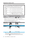
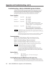
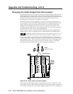
Troubleshooting a Matrix 3200/6400 System Problem
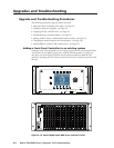
All Matrix 3200/6400 BME front panels include LEDs at the bottom of the panel
which are bracketed and labeled DIAGNOSTICS. These LEDs (Figure 5-6.A)
indicate the current status of the BME power supplies, the RS232/BME/MKP
1
Communications RX and TX lines, and the System Status. The following
descriptions include normal/failure/status conditions for each LED.
Power Supplies
Primary +V Green LED ON = Normal
OFF = Failure
Primary -V Green LED ON = Normal
OFF = Failure
Redundant +V Green LED ON = Normal
OFF = Failure (or Redundant not present)
Blinking = Redundant +V supplying full +V load
(indicates Primary +V power supply failure)
Redundant -V Green LED ON = Normal
OFF = Failure (or Redundant not present)
Blinking = Redundant -V supplying full +V
load (indicates Primary -V power supply failure)
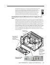
If a BME fails to power ON, check the BME external AC fuse (see Page 5-7).
If the Diagnostic LEDs indicate that a power supply has failed, check the power
supply fuse (see Page 5-7).
BME #0 must be powered ON at the same time or after other BMEs. Any BME
powered on after BME #0 will not be seen by the internal system software.
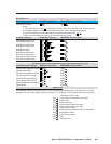
Communications
RS232 TX - Red LED ON/Blinking = BME is transmitting data to Host
RS232 RX - Green LED ON/Blinking = BME is receiving data from Host
BME TX - Red LED ON/Blinking = BME is transmitting data
BME RX - Green LED ON/Blinking = BME is receiving data
MKP TX - Red LED ON/Blinking = BME is transmitting to Remote keypad
MKP RX - Green LED ON/Blinking = BME is receiving from Remote keypad
1. MKP TX/RX LEDs are not present on SYNC BMEs.
2. MKP LED conditions above apply only to BME #0.
3. RS-232 LED conditions above apply only to BME #0.
4. A communications failure between BME #0 and other BMEs could be
caused by one BME loading down the BME TX or RX line. To determine if
that is the case, run the RJ-11 BME COMM interconnecting cable to bypass
each BME one at a time.
System Status
Amber LED ON = Normal
OFF = System failure - Call Extron Tech Support
Blinking = Busy
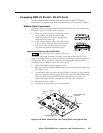
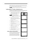
Checking/Replacing the BME External AC Input Fuse
The AC power input cord plugs into the Power-Switch/Fuse assembly which is
located on the rear panel in the lower left corner of the BME. To check/replace the
external fuse, remove the power-cord and insert the tip of a small screwdriver blade