Installation, cont’d
Matrix 3200/6400 Series • Installation2-6
AC POWER INPUT
FUSE: 250V 5.0A TT
IN
OUT
100-240V 5.0A MAX 50/60Hz
DISCONNECT POWER CORD BEFORE SERVICING
MKP COMM.BME COMM. RS232/RS422
A
B
C
D
E
A
B
C
D
E
BME
ADDRESS
ANAHEIM, CA
MADE IN USA
4
-
+
INPUTS OUTPUTS
IN
1 - 8
IN
9 - 16
IN
17 - 24
IN
25 - 32
IN
33 - 40
IN
41 - 48
IN
49 - 56
IN
57 - 64
OUT
1 - 8
OUT
9 - 16
OUT
17 - 24
OUT
25 - 32
OUT
33 - 40
OUT
41 - 48
OUT
49 - 56
OUT
57 - 64
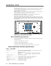
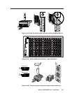
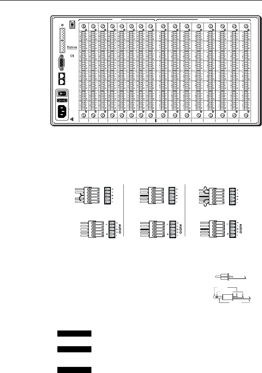
Figure 2-4.B shows three methods of wiring the stereo connectors, with input
examples across the top, output examples below.
Figure 2-4.B Three ways to wire stereo input and output audio
connectors (see cautions below).
When making connections for the Matrix 6400 Audio switcher from existing audio
cables, see Figure 2-4.C. The round audio connectors are
shown with the top one (tip and sleeve only) for
unbalanced audio and the bottom one (tip, ring and
sleeve) for balanced audio. The "ring", "tip" and "sleeve"
markings are also used on the captive screw
audio connector diagrams in Figure 2-4.C.
Together, these examples may be used as a guide for
making audio cables.
CAUTION
Do not connect equipment that uses phantom power.
Tip
Sleeve
Ring (-)
Tip (+)
Sleeve
Figure 2-4.C
Examples of Audio
Cable Connectors
CAUTION
Connect the sleeve to ground (Gnd). Connecting the sleeve to a negative
(-) terminal will damage the audio output circuits.
CAUTION
There is no physical way to prevent you from plugging a stereo audio
connector partially in one input and partially in the adjacent input. This
could cause circuit damage.
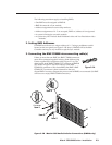
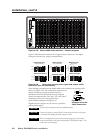
Figure 2-4.A Matrix 6400 Audio Switcher - Stereo backplane
LR
AUDIO
LR
AUDIO
LR
AUDIO
Unbalanced Input
Tip
Sleeve
Tip
Sleeve
Balanced Input
Tip
Ring
Sleeve (s)
Tip
Ring
Tip
Ring
Sleeve (s)
Tip
Ring
Balanced Input
(high impedance)
(high impedance)
(600 ohms)
600 ohms
600 ohms
Unbalanced Output
Tip
See caution
Sleeve
Tip
See caution
Balanced Output
Tip
Ring
Sleeve (s)
Tip
Ring
Balanced Output
Tip
Ring
Sleeve (s)
Tip
Ring


