


Extron • System 4
xi
Switcher Series • User’s Manual
Chapter 2 • Configuration and Installation
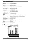
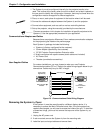
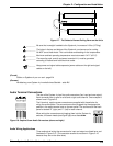
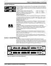
2. If your unit is not set up correctly, remove the System 4xi cover (page 2-3) and
locate the switches and projector connectors. Note the orientation of the SW1
switches in the picture. “On” is marked on the DIP switch block.
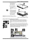
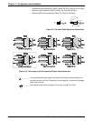
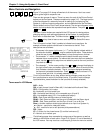
3. Set the switches as indicated by the label or the instructions included with the
projector communications kit and verify that the Projector cable is on the correct
connector (J9/J15).
_______ Extron continues to support new projectors. If you have questions about using
the System 4
xi
with a device for which you cannot find configuration settings,
please consult with your Extron representative.
4. Refer to the appropriate cabling procedure included with the projector
communications kit to continue the installation.
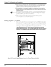
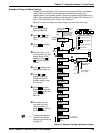
Cabling a System 4xi in a Rack
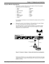
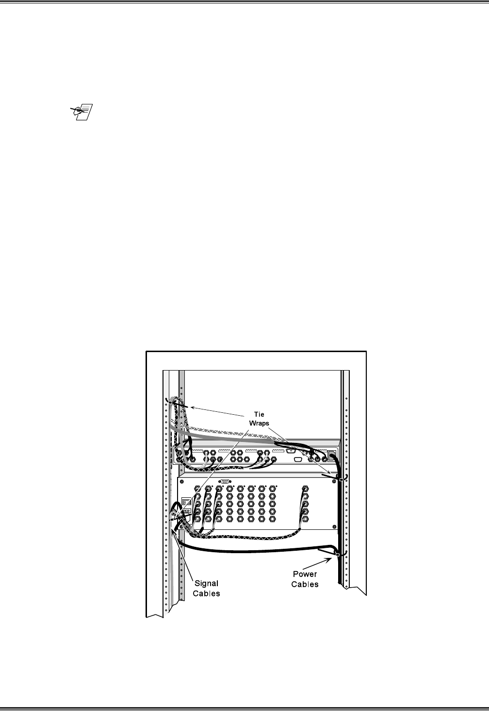
When routing cables from one unit to another in a rack, do NOT allow the cables
to be supported by the System 4xi (see Figure 2-7). Use “Tie Wraps”, “Rip-Ties”
or other devices, to secure the cables at some point in the rack that is above the
rear panel connectors. Loosely hanging cables may be stepped upon, resulting
in damage to cables and equipment, as well as injury to personnel.
The example shown in Figure 2-6 has the cables tied to the rack above the
connections to the equipment. This allows an unobstructed view of the rear panel
connectors, and prevents the cable weight from pulling down on the equipment.
2-5
Figure 2-6. Route the Signal Cables on the Left and Power Cables on the Right