


Extron • System 4
xi
Switcher Series • User’s Manual
Chapter 2 • Configuration and Installation
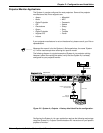
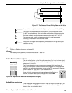
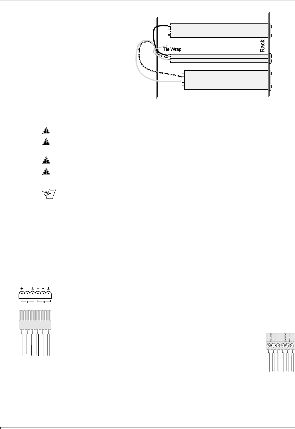
Figure 2-7. Tie Cables to Prevent Pulling Down on the Units
_________ Be sure that no weight is added to the System 4
xi
in excess of 10 lbs (3.73 kg).
_________ The holes in the top and bottom of the System 4
xi
enclosure are for cooling.
Do NOT cover these holes. This could cause overheating of vital components.
_________ Maximum ambient operating temperature must not exceed 104° F (40° C).
_________ The mounting rack, and all equipment mounted in it, must be grounded
according to national and local electrical codes.
_______ Keep power and signal cables separate (power cables on the right and signal
cables on the left.)
(French)
Câbler un Système 4
xi
sur un rack - page B-4
(German)
Verkabelung vom System 4
xi
innerhalb eines Gestells - seite B-6
2-6
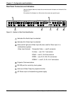
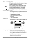
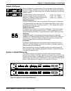
Audio Terminal Connections
The rear of the System 4xi has five audio connectors (four input and one output).
Each connector has six pins for a left and a right audio channel. One example is
shown here in Figure 2-8.
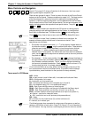
The 6-terminal, captive screw connectors are supplied with the switcher for
wiring the audio cables. The connectors are then plugged into the appropriate
position in the audio terminal strip on the rear panel. The audio area of the back
panel is labeled “R” (right) and “L” (left) for each channel.
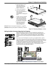
When wiring the connectors and plugging them into the System 4xi
switcher, the screw heads (see figure right) must face down.
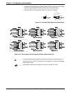
Figure 2-8. Captive Screw Audio Connectors (above and right)
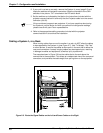
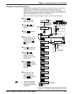
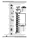
Audio Wiring Applications
Three methods of wiring the connectors for input and output are listed here, and
illustrated in Figure 2-10. (The connector screws do not show in Figure 2-10
because they are on the other side.)