


IPL M PDP-ES • Installation and Operation
IPL M PDP-ES • Installation and Operation
Installation and Operation, cont’d
2-7
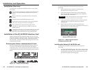
Resetting the unit
There are five reset modes available by using the Reset button
(
5
) on the front panel. The Reset button is recessed, so use of
a pointed stylus, ballpoint pen, or Extron Tweeker is suggested.
CAUTION
Review the reset modes carefully. Use of the wrong
reset mode may result in unintended loss of flash
memory programming, reassignment of ports, or a
IPL M PDP-ES reboot.
CAUTION
The listed reset modes (with the exception of
mode 2) closes all open IP connections to the unit.
If the reset button is continuously held down, every three
seconds the LED pulses (blink) and puts the unit in a
different reset mode, corresponding to the underscored
notes in modes 3 through 5. The mode 5 LED blinks
three times, the third blink indicating that it’s the last
mode.
The following modes are listed as separate functions, not
as a continuation from mode 1 to mode 5.
Mode 1 — Holding the reset button while applying power
defaults the unit back to the base firmware that shipped
with the unit from the factory. Event scripting does not
start when the unit is powered on in this mode. This
allows you to recover a unit that has incorrect code or
updated firmware running. All user files and settings are
maintained. User Web pages may not work correctly with
an earlier firmware version.
Mode 2 — Momentarily (<1 second) pressing the reset button
and entering three “+”s into the RS-232 port of the
interface card (e.g., “+++” within 2 seconds of the
momentary press) enables the connected COM port to be
used as a console port to send SIS commands. If the three
“+”s are not entered in the 2 second time frame, the COM
port remains or returns to being a control port only.
A mode 2 reset disconnects a pass-through connection.
Mode 3 — Holding the reset button until the Power LED
blinks
once (3 seconds), followed by a momentary
(<1 second) press turns events either On or Off,
depending on the current state of the events:
• If the events are currently stopped following the
momentary (<1 second) press, the Power LED flashes
twice, indicating the starting of events.
2-6
5
Reset button (recessed) — See Resetting the unit, later in
this chapter, for additional details on this multiple function
reset button.
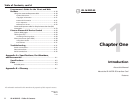
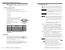
RS-232 communication
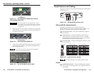
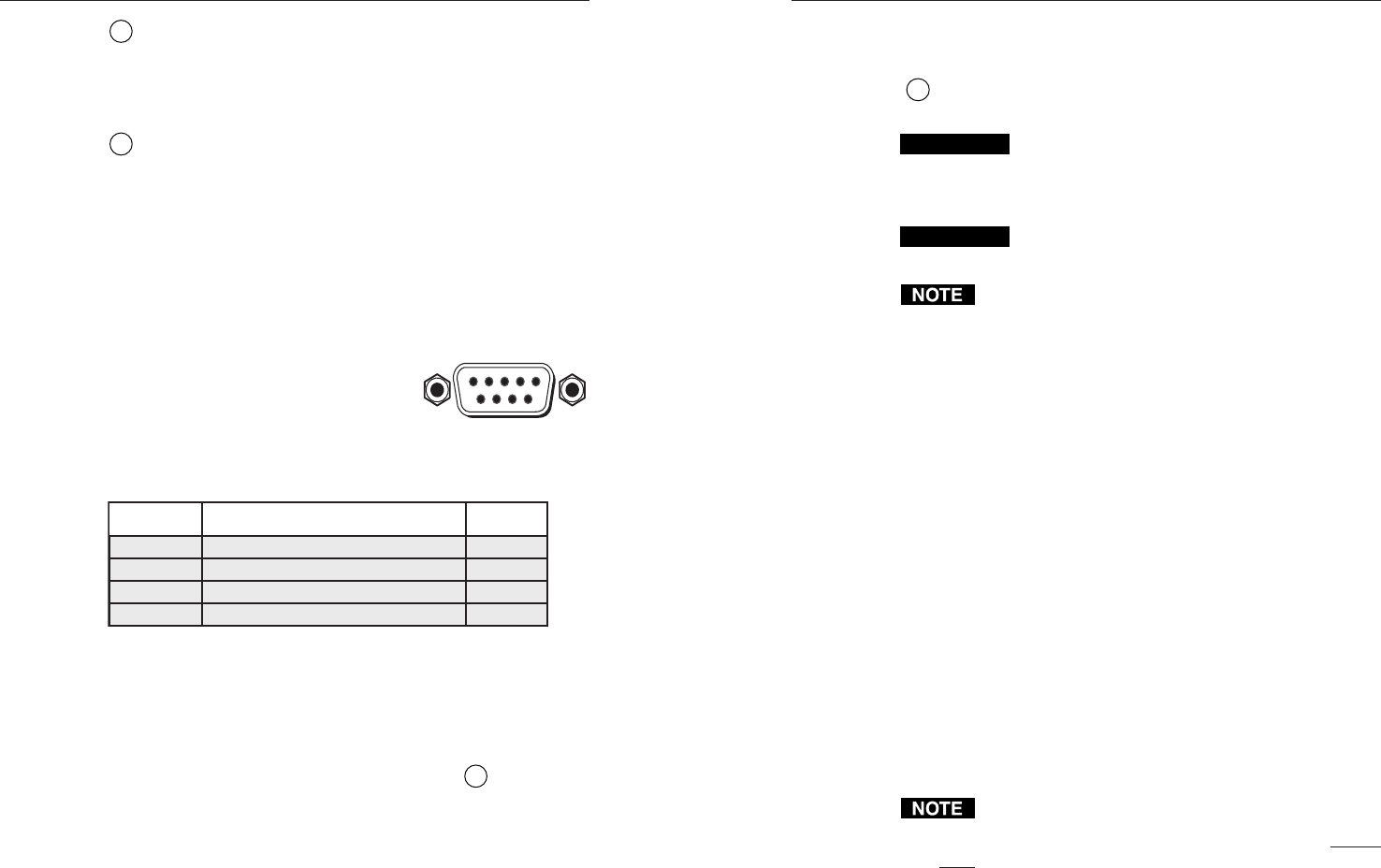
6
RS-232 port — Plug a serial cable into this 9-pin D
connector for a serial connection.
Factory default protocol for the IPL M PDP-ES interface card is
• 9600 baud
• No parity
• 8 data bits
• 1 stop bit
This port accepts Pioneer’s standard RS-232
commands and passes them through to
the display. Contact Pioneer for a list of
current commands.
See the chart below for the pin
assignments of the 9-pin D connector
RS-232 port.
Pin Function
RS-232
2
3
5
1, 4, 6, 7, 8, 9
Receive Data/Receive Data -
Transmit Data/Transmit Data -
Signal Ground
Not Connected
TX
RX
GND
NC
Figure 2-8 — RS-232, 9-pin D connector pin
assignments
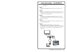
Operation
Once the IPL M PDP-ES has been successfully installed and
cabled, check the unit’s On/Off indicator LED (
4
) to ensure
that the card is plugged in and communicating. At this point,
the IPL M PDP-ES is ready to be configured (see chapter 3,
Connection and Configuration).
If connection or communication problems occur, see
Troubleshooting in chapter 4. If the troubleshooting tips do not
help, check with your local network administrator, or call the
Extron S
3
Sales & Technical Support Hotline.
DB9 Pin Locations
(Female)
51
96