


IPL M PDP-ES • Installation and Operation
IPL M PDP-ES • Installation and Operation
Installation and Operation, cont’d
2-5
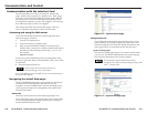
Panel Features and Cabling
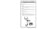
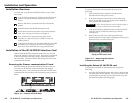
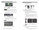
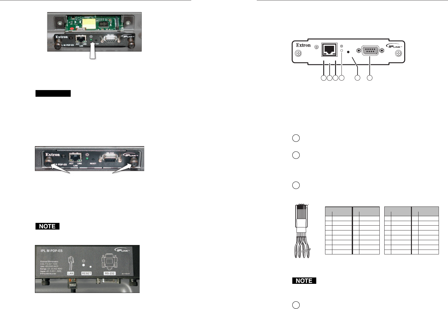
See figure 2-6 below for detailed information about connections,
LEDs, and power.
IPL M PDP-ES
ACT LINK
RESET
LAN
RS-232
4
6
5
2
1
3
Figure 2-6 — IPL M PDP-ES interface card
Ethernet/LAN communication
With the use of Ethernet/LAN communication, the
IPL M PDP-ES can be used to control the plasma display. See
chapter 4, Communication and Control, for more details.
1
LAN Activity LED — The yellow LED blinks to indicate
LAN activity.
2
LAN connector — Plug an RJ-45 jack into this socket to
connect the unit to a computer network. Use a straight-
through cable to connect to a switch, hub, or router; and a
crossover cable to connect directly to a PC.
3
LAN Link LED — The green LED lights to indicate a good
LAN connection.
Clip Down
1
1&2
3&6
4&5
7&8
2345678
12345678
RJ-45
connector
Straight-through cable
Twisted
Pairs
Side 1 Side 2
Pin Wire color Pin Wire color
1 White-orange 1 White-orange
2 Orange 2 Orange
3 White-green 3 White-green
4 Blue 4 Blue
5 White-blue 5 White-blue
6 Green 6 Green
7 White-brown 7 White-brown
8 Brown 8 Brown
Crossover cable
Side 1 Side 2
Pin Wire color Pin Wire color
1 White-orange 1 White-green
2 Orange 2 Green
3 White-green 3 White-orange
4 Blue 4 Blue
5 White-blue 5 White-blue
6 Green 6 Orange
7 White-brown 7 White-brown
8 Brown 8 Brown
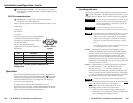
Figure 2-7 — RJ-45 connector wiring
For best performance, use a shielded Ethernet cable.
Power
4
On/Off indicator LED — The green LED lights to indicate
that the card is receiving power. It also indicates different
reset modes.
2-4
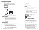
Figure 2-3 — Inserting the IPL M PDP-ES card into
the communication slot
CAUTION
Be very careful when inserting the card. Do not
use excessive force, and push the card in as straight
as possible; a crooked entry could damage the card
or the plasma.
2. When the card is seated securely in the slot, use the spring
loaded thumb screws on either end of the card faceplate to
secure the card in place.
Figure 2-4 — Securing the IPL M PDP-ES
3. Affix the Extron IPL M PDP-ES sticker label (Extron part #
33-1154-01) to the display, covering the existing Pioneer
label, as shown below.
Insure that the sticker is placed so that it completely
covers the existing Pioneer label.
Figure 2-5 — The IPL M PDP-ES sticker label
Push gently
Thumb screws