


MPS Series • Installation
2-3
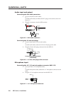
5. Align the mounting screws with the slots in the brackets and place the
switcher against the surface, with the screws through the bracket slots.
6. Slide the switcher slightly forward or back, then tighten all four screws to
secure the switcher in place.
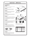
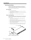
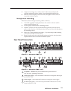
Through-desk mounting
Mount the switcher through a desk or podium as follows:
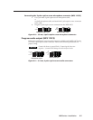
1. Attach the supplied mounting brackets to the switcher with the machine
screws provided (figure 2-1).
2. Cut the proper sized hole in the mounting surface.
3. Hold the switcher with the attached brackets against the underside of the
table or other furniture. Mark the location of the screw holes of the bracket on
the mounting surface.
4. Drill 3/32" (2 mm) diameter pilot holes, 1/4" (6.3 mm) deep in the mounting
surface at the marked screw locations.
5. Insert four #8 wood screws through the bracket and into the four pilot holes.
Tighten all four screws to secure the switcher in place.
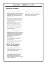
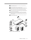
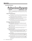
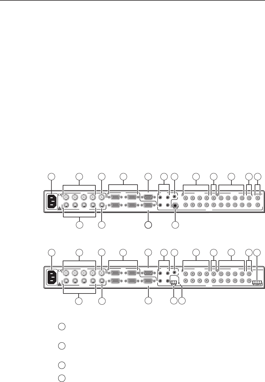
Rear Panel Connectors
50/60 Hz
100-240V 0.5A MAX
(VIDEO)
MPS 112
PROG OUT
OUT4321
OUT
OUT
OUT
RS-232
432
2
1
1
2
1
4
3
4
3
L
R
OUT4321
(S-VIDEO)
AUDIO
VIDEO VGA (VGA)
MIC IN
S-VIDEO
2 6 14 1693
5
7
8
11
10
4
1 15 17 18
Figure 2-2 — Rear panel of MPS 112
50/60 Hz
100-240V 0.5A MAX
(VIDEO)
MPS 112CS
PROG OUT
OUT4321
OUT
OUT
OUT
RS-232
432
2
1
1
2
1
4
3
4
3
L
R
OUT4321
(S-VIDEO)
AUDIO
VIDEO VGA (VGA)
(S-VIDEO)
LR
PHANTOM
POWER
MIC IN
2
6
14
16
9
8
10 191 15 17
5
7
12
4
13
3
Figure 2-3 — Rear panel of MPS 112CS
1
AC power — Standard AC power connector for a power source of
100 – 240 VAC, operating at 50/60 Hz.
2
Video input group — Four female BNC connectors for composite video input
(numbered 1 to 4).
3
Video output — One female BNC connector for composite video output.
4
S-video input group — Four female 4-pin mini DIN connectors for S-video
input (numbered 1 to 4).