


Installation, cont’d
MPS Series • Installation2-8
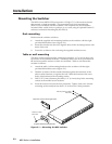
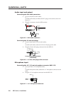
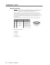
DB9 Pin Locations
Female
51
96
Remote connection
The cable used to connect the RS-232/Remote port to a computer or control
system may need to be modified by removing pins or cutting wires. If
unneeded pins are connected, the switcher may hang up.
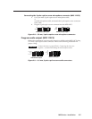
For RS-232 control, use a control cable with only pins 2, 3, and 5 connected.
Otherwise, either cut the wires to the other pins in hard-shelled connectors or
remove the unneeded pins from molded plugs. See chapter 5, Programmer’s Guide,
for definitions of the SIS commands and details on how to install and use the
control software.
The RS-232 connector is a 9-pin D female with the following pin designations:
Pin RS-232 function Description
1 – No connection
2 Tx Transmit data
3 Rx Receive data
4 – No connection
5 Gnd Signal ground
6, 7 – No connection
8, 9 – No connection
The protocol is as follows:
• 9600 baud
• 8-bit data
• 1 stop bit
• no parity
• no flow control.