


MPS Series • Programmer’s Guide
5-3
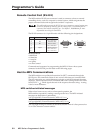
MPS switcher error responses
When the MPS switcher receives an SIS command and determines that it is valid, it
performs the command and sends a response to the host device. If the switcher is
unable to perform the command because the command is invalid or contains
invalid parameters, it returns an error response to the host. The error response
codes are as follows:
E01
— Invalid input channel number (too large)
E10
— Invalid command
E13
— Invalid value (out of range)
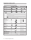
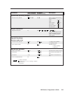
Using the command/response table
The command/response table is shown on the following pages. Lower case
characters are acceptable in the command field only where indicated. Symbols are
used throughout the table to represent variables in the command/response fields.
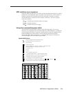
Symbol definitions are shown below, and an ASCII-to-hexadecimal (HEX)
conversion table is shown in figure 5-1. Command and response examples are
shown throughout the command/response table.
Symbol definitions
= CR/LF (carriage return/line feed) (hex 0D 0A)
= Carriage return (no line feed, hex 0D)
• = Space character
Esc
= Escape key (hex 1B)
X1
= Group 1 through 3 (1 = VGA, 2 = S-video, 3 = composite video)
X2
= Inputs 0 through 4 for each group (input 0 = off)
X3
= 0 = off and 1 = on
X4
= 0 to 12
X5
= 1 to 66
X6
= -66 to +12 (dB mic gain level)
X7
= 1 = Single Switcher mode, 2 = Separate Switcher mode
X8
= 0 through 15, default = 8 (mic talk-over threshold level)
X9
= 0 through 12 (input number in Simple address)
= 0 - 82 (program volume adjustment range)
X11
= Inputs 0 through 12 for single input addressing,
X11
= (
X1
- 1) times 4 +
X2
= Control software version to the second decimal place
ASCII to HEX Conversion Table
•
Figure 5-1 — ASCII-to-hexadecimal conversion table