2-7MPS Series • Installation
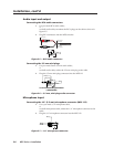
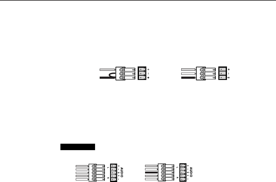
Connecting the 3-pole captive screw microphone connector (MPS 112CS)
1. Use a pre-made 3-pole captive screw microphone cable,
or
cut bulk microphone cable, and attach the 3-pole captive screw connector
to the cable.
2. Plug the 3-pole captive screw connector into the MPS 112CS.
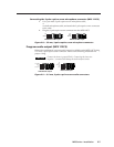
Balanced Mic InputUnbalanced Mic Input
Tip
Ring
Sleeve
Tip
Sleeve
Figure 2-8— 3.5 mm, 3-pole captive screw microphone connector
Program audio output (MPS 112CS)
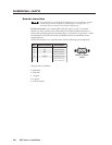
Balanced or unbalanced program audio output is available on the MPS 112CS using
a 3.5 mm, 5-pole captive screw connector. Refer to the following illustration for
proper wiring.
CAUTION
Connect the sleeve to ground (Gnd). Connecting the sleeve to a
negative (-) terminal will damage the audio output circuits.
Unbalanced Output
Tip
See caution
Sleeve
Tip
See caution
Balanced Output
Tip
Ring
Sleeve (s)
Tip
Ring
Figure 2-9 — 3.5 mm, 5-pole captive screw audio connectors


