


Programmer’s Guide
MPS Series • Programmer’s Guide
5-2
Remote Control Port (RS-232)
The MPS switcher RS-232 port connector is used to connect to a host or external
controlling device, such as a computer or control system, which can generate the
proper command codes and recognize the switcher’s responses.
The cable used to connect the RS-232 port to a computer or control system may
need to be modified by removing pins or cutting wires. If unneeded pins are
connected, the switcher may hang up. See chapter 2, Installation, for more
information on wiring the connectors.
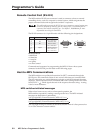
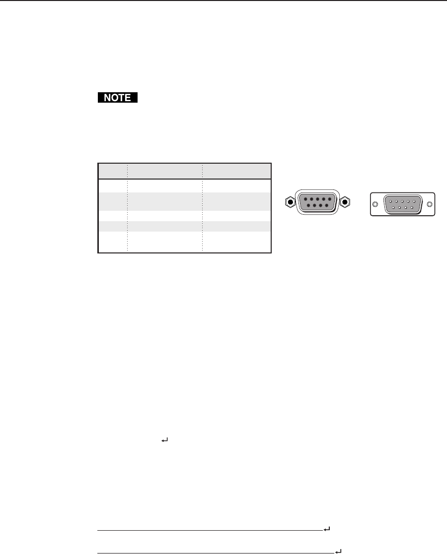
The RS-232 connector is a 9-pin D female with the following pin designations:
Pin RS-232 function Description
1 – No connection
2 Tx Transmit data
3 Rx Receive data
4 – No connection
5 Gnd Signal ground
6, 7 – No connection
8, 9 – No connection
51
9
5
9
6
Female Male
1
6
RS-232 protocol:
• 9600 baud
• 8 data bits
• 1 stop bit
• no parity
• no flow control
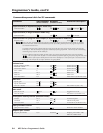
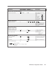
Commands and responses for programming the MPS 112 from a host system
connected to the RS-232 port are listed on the following pages.
Host-to-MPS Communications
The MPS switchers accept Simple Instruction Set (SIS
™
) commands through the
RS-232 port. SIS commands consist of one or more characters per command field.
They do not require any special characters to begin or end the command character
sequence. Each response to an SIS command ends with a carriage return and a line
feed (CR/LF =
), which signals the end of the response character string. A string
is one or more characters.
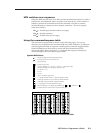
MPS switcher-initiated messages
When a local event occurs, such as a front panel operation, the
MPS switcher responds by sending a message to the host. The MPS -initiated
messages are listed below (underlined).
(c) Copyright 2003, Extron Electronics, MPS 112, Vx.xx
or
(c) Copyright 2003, Extron Electronics, MPS 112CS, Vx.xx
The copyright message is initiated by the MPS switcher when it is first powered on.
Vx.xx is the firmware version number.