


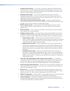
Installation
This section describes the installation and the operation of the MPS 409, including:
• Mounting the Switcher
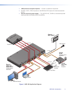
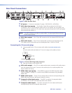
• Rear Panel Connections
• Cabling the MPS 409 Switcher
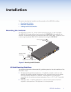
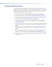
Mounting the Switcher
The MPS 409 is housed in 1U, full rack width metal enclosure rack- or desk-mountable.
The MBD 149 1U through-desk and rack mounting kit (#70-077-03) is included with the
switchers. The switchers may also be surface-mounted under a table, desk, or podium, or on
a wall, using the optional MBU 149 1U under-desk mounting kit (#70-222-01).
50/60 Hz
100-240V .2A
L R
Tx
MIC/LINE
IN
ON
OFF
MI
C
LINE
ON
1 2
HDMI
VIDEO
VGA/YUV
D
VI-D
OUTPUT
OUTPUT
OUTPUT
OUTPUT
OUTPUT
OUTPUT
OUTPUT
1
2
L
1
2
1
2
1
2
1
2
1
2
1
2
3
3
1
2
L L
R
R
R
MIC/LINE
PROGRAM
A
UDIO
OU
T
Rx
RS-232
OUTPUT
100-240V 0.2A
50-60Hz
100-240V 0.2A
50-60Hz
100-240V 0.2A
50-60Hz
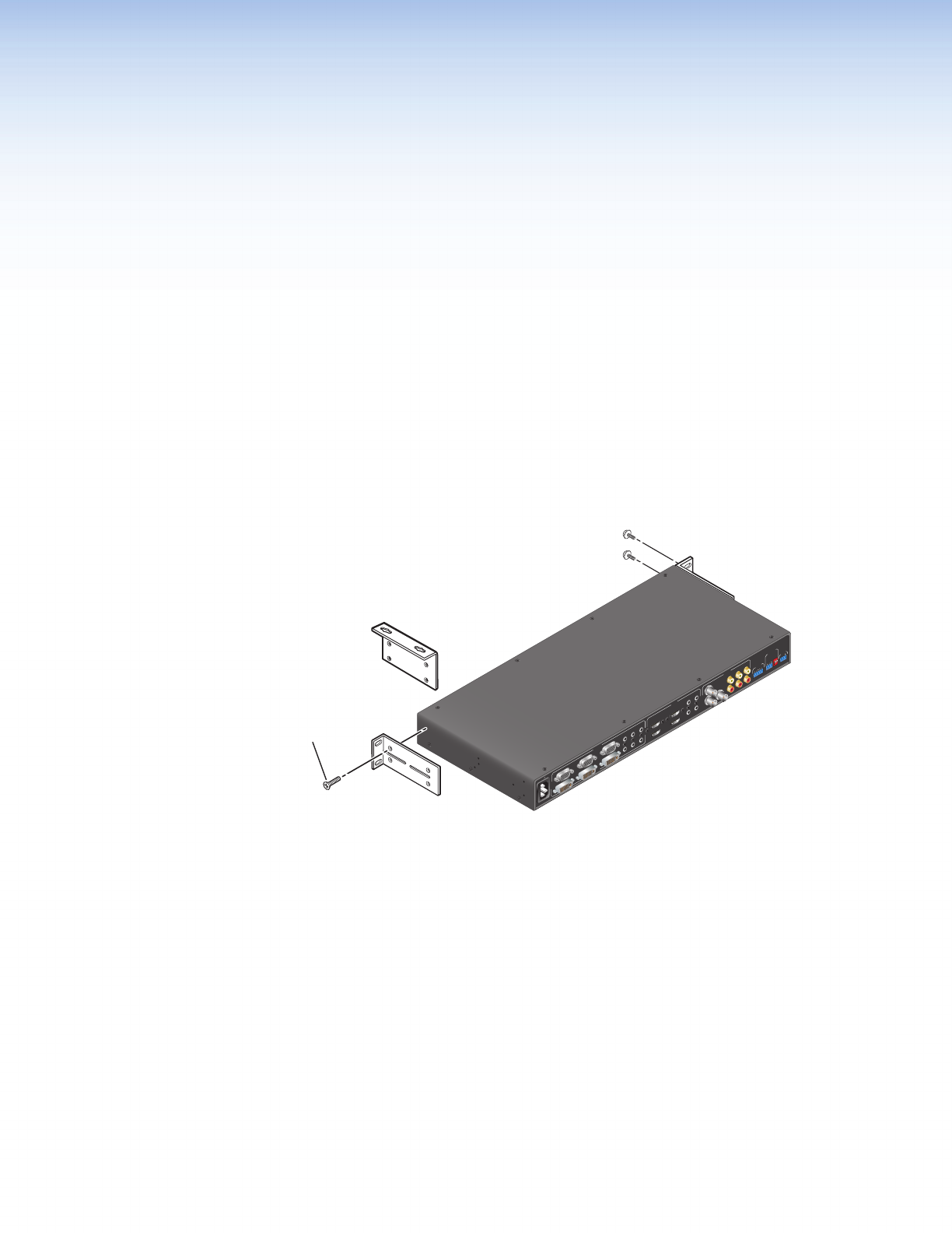
Mounting Screws (2 Plcs)
Each Side
Optional Furniture Mounting Bracket
-or-
Supplied Rack Mounting Bracket
#8 Screw (4 Plcs)
Each Side
Figure 2. Mounting the MPS Switcher
UL Rack Mounting Guidelines
The following Underwriters Laboratories (UL) guidelines pertain to the safe installation of the
MPS 409 in a rack.
1. Elevated operating ambient temperature — If installed in a closed or multi-unit rack
assembly, the operating ambient temperature of the rack environment may be greater
than room ambient temperature. Therefore, install the device in an environment
compatible with the maximum ambient temperature (Tma = +122 °F, +50 °C) specified
by Extron.
2. Reduced air flow — Install the equipment in a rack so that the amount of air flow
required for safe operation of the equipment is not compromised.
MPS 409 • Installation 4