


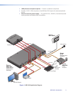

Cabling the MPS 409 Switcher
The MPS switcher can be connected to as many as 9 input devices simultaneously. It can
output to as many as four devices (three in combine mode) simultaneously. Outputs can be
configured for simultaneous outputs from each of the four input groups, VGA/YUV, DVI-D,
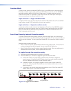
HDMI, composite or one at a time from a selection of the nine inputs. Follow the steps
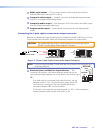
below and see the installation example in figure 1.
1. Turn off power to the MPS switcher and all devices that will be connected to it.
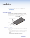
2. If the MPS switcher is to be rack, table/wall, or through-desk mounted, position the
brackets and insert the mounting screws. See Mounting the Switcher on page 4.
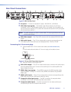
3. Attach up to two VGA, three HDMI, two DVI-D, and two composite video input devices
to the MPS switcher. See Rear Panel Connections on page 6.
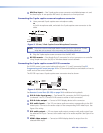
4. Connect the switcher VGA, HDMI, DVI and Composite video outputs (up to four,
one of each video format) to the appropriate display device inputs. See Rear Panel
Connections on page 6.
5. For stereo audio input, connect up to 9 audio sources to the corresponding audio inputs
of the VGA, HDMI, DVI, or composite video groups. See Rear Panel Connections on
page 6.
6. For stereo output, connect an audio output device to each of the four groups and an
audio amplifier to the Program Audio connectors. See Rear Panel Connections on
page 6.
7. If the switcher is to be connected to a computer or host controller for remote control,
connect the host RS-232 cable to the 3-pole captive screw connector (
k
) of the
switcher. For an RS-232 pinout table, see Remote Control Port (RS-232) on page 20 .
8. Power up the input and output devices, then connect power to the rear AC connector
of the MPS switcher.
MPS 409 • Installation 9