


USB Configuration Port
Drivers for the MPS 409 USB configuration port are loaded automatically when Dataviewer
or Firmware Loader, included on the software disc or available at www.extron.com, are
loaded.
Host-to-MPS Communications
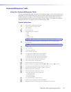
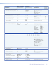
The MPS switcher accepts Simple Instruction Set (SIS
™
) commands through the RS-232 or
USB configuration port. SIS commands consist of one or more characters per command field.
They do not require special characters to begin or end the command character sequence.
Each response to an SIS command ends with a carriage return and a line feed (CR/LF =
]
),
which signals the end of the response character string. A string is one or more characters.
MPS Switcher-initiated Messages
When a local event occurs, such as a front panel operation, the MPS switcher responds
by sending a message to the host. The MPS 409-initiated messages are listed below
(underlined).
Boot-up messages
(c) Copyright 2010, Extron Electronics, MPS 409, Vx.xx
]
The copyright message is initiated by the switcher when it is first powered on. Vx.xx is the
firmware version number.
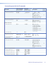
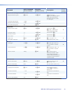
Status change messages
The switcher-initiated status change messages are a result of front panel operations (actual
or software-simulated). The status change messages are the same as switcher responses to
certain commands. See the last column of the command/response tables on the following
pages.
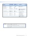
MPS Switcher Error Responses
When the MPS switcher receives an SIS command and determines that it is valid, it performs
the command and sends a response to the host device. If the switcher is unable to perform
the command because the command is invalid or contains invalid parameters, it returns an
error response to the host. The error response codes are as follows:
E01
]
— Invalid input channel number (too large)
E10
]
— Invalid command
E13
]
— Invalid value (out of range)
MPS 409 • SIS Programming and Control 21