


j
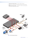
Mic/Line input — One 3-pole captive screw connector switchable between mic and
line level inputs. A two position DIP switch (u) selects mic or line input level.
Connecting the 3-pole captive screw microphone connector
1. Use a pre-made 3-pole captive screw microphone cable,
or
cut bulk microphone cable, and attach the 3-pole captive screw connector to the
cable.
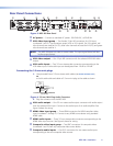
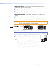
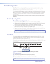
Balanced Mic Input
Unbalanced Mic Input
Tip
Ring
Tip
Sleeve Sleeve
Do not tin the wires!
Figure 5. 3.5 mm, 3-Pole Captive Screw Microphone Connector
NOTE: Do not tin the mic wire leads before installing into the connector. Tinned
wires are not as secure in the connector and could be pulled out.
2. Plug the 3-pole captive screw connector into the MPS 409.
k
RS-232 remote — One female 9-pin D connector for a host computer or a controller
using Simple Instruction Set (SIS) or Windows-based control software.
Connecting the 3-pole captive screw RS-232 connector
For RS-232 control, use a control cable with only pins 2, 3, and 5 connected. See SIS
Programming and Control on page 20 for SIS commands definitions and details on how to
install and use the control software.
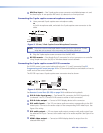
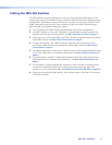
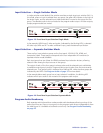
The RS-232 input uses a 3-pole captive screw connector wired as shown:
Ground ( _ )
Receive (Rx)
Transmit (Tx)
Bidirectional
RS-232
Device
Ground ( _ )
Receive (Rx)
Transmit (Tx)
RxTx
Do not tin
the wires!
Figure 6. RS-232 Captive Screw Connector Wiring
See Remote Control Port (RS-232) on page 20 for additional wiring details.
l
DVI-D video input group — Two female DVI connectors for DVI-D signals only
(numbered 1 and 2). Connect DVI-D sources to either or both connectors.
m
DVI-D video output — Connect a DVI-D display device to this connector.
n
DVI audio inputs — Two 3.5 mm stereo audio connectors corresponding to the DVI
video inputs. Connect to the audio output of the corresponding DVI-D video input. See
figure 4 for wiring.
o
DVI audio output — 3.5 mm stereo audio output connector with audio output from
the selected DVI input. Connect to the audio input of an audio amplifier. See figure 4 for
wiring.
p
HDMI video output — Connect an HDMI display device for output from the
selected HDMI input.
MPS 409 • Installation 7