


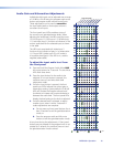
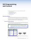
SIS Programming
and Control
This section discusses SIS programming and control of the MPS 409 including:
• Connection Options
• Host-to-MPS Communications
• Command/Response Table
• Updating Firmware
Connection Options
The MPS 409 can be remotely connected via a host computer or other device (such as a
control system) attached to the rear panel RS-232 port or the front panel USB Config port.
The switcher can be set up and controlled using SIS (Simple Instruction Set) commands. SIS
commands may be executed using the Extron DataViewer program, found on the Software
Products DVD included with the product or at www.extron.com.
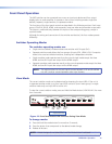
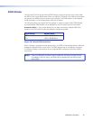
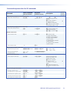
Remote Control Port (RS-232)
The MPS switcher RS-232 port connector (3-pole captive screw) is used to connect to a host
or external controlling device, such as a computer or control system, which can generate the
proper command codes and recognize switcher responses.
NOTE: The cable used to connect the RS-232 port to a computer or control system
may need to be modified by removing pins or cutting wires. If unneeded
pins are connected, the switcher may hang up. See Connecting the 3-pole
captive screw RS-232 connector on page 7, for more information on wiring
the connectors.
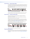
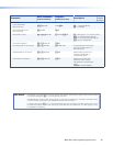
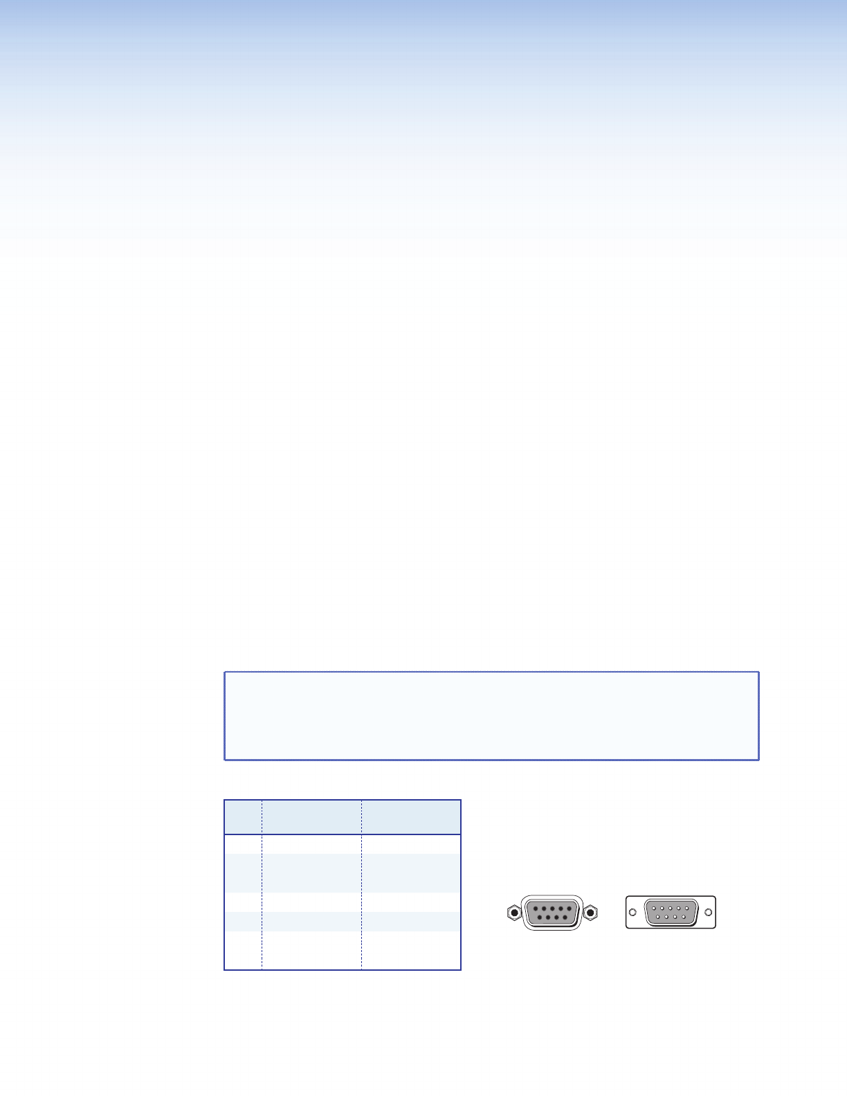
The RS-232 connector on the PC is a 9-pin D female with the following pin designations:
Pin
RS-232
function
Description
1 - No connection
2 Tx Transmit data
3 Rx Receive data
4 - No connection
5 Gnd Signal ground
6,7 - No connection
8,9 - No connection
Commands and responses for programming the MPS 409 from a host system connected to
the RS -232 port are listed later in this chapter.
5 1
9
5
9
6
Female Male
1
6
MPS 409 • SIS Programming and Control 20