


q
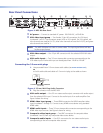
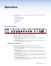
HDMI audio output — 3.5 mm stereo connector with audio output from the
selected HDMI input. See figure 4 for wiring.
r
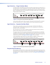
Composite video output — One BNC connector with selected composite video
output for a composite video display device.
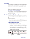
s
Composite audio output — One stereo pair of RCA connectors with audio output
from the selected composite video input.
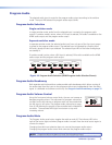
t
Program audio output — 5-pole captive screw connector with selected audio
output.
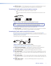
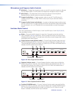
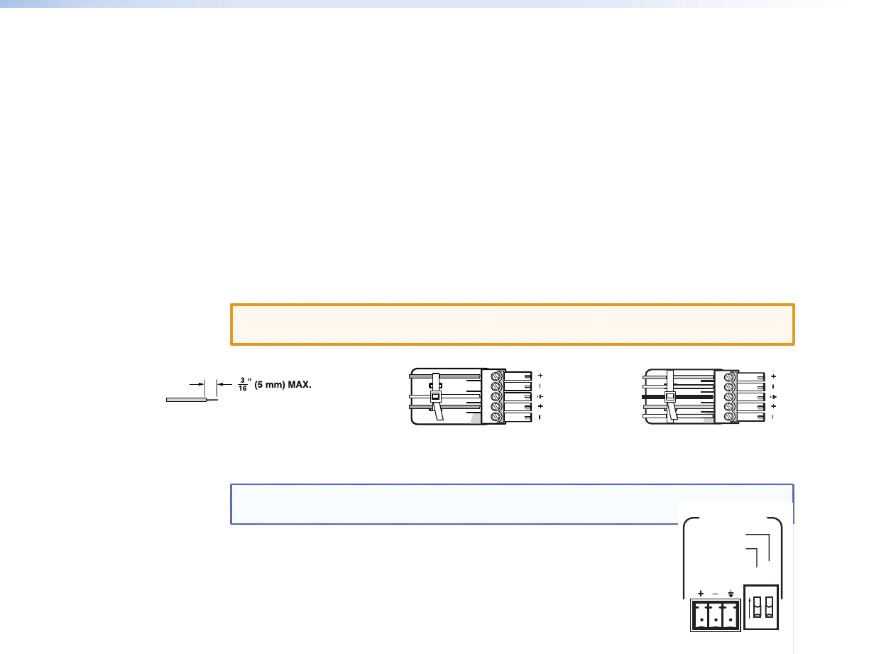
Connecting the 5-pole captive screw stereo output connector
Balanced or unbalanced program audio output is available on the MPS 409 using a 3.5 mm,
5-pole captive screw connector. Refer to the following illustration for proper wiring.
CAUTION: For unbalanced audio output, connect sleeves to the center ground pin.
DO NOT connect sleeves to the negative (-) contacts.
Tip
NO Ground Here
Sleeve(s)
NO Ground Here
Tip
L R
Unbalanced Audio Output Balanced Audio Output
Tip
Ring
Tip
Ring
L R
Sleeve(s)
Do not tin the wires!
Figure 7. 3.5 mm, 5-Pole Captive Screw Audio Output Connectors
NOTE: Do not tin the audio leads. Tinned wires are not as secure in the connector and
could be pulled out.
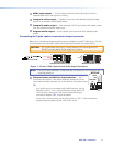
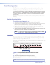
u
Phantom Power and Mic/Line Input selection — Two
2-position DIP switches. +48V selects phantom power for the mic
input and level selects between mic or line level for the mic/line input
(
j
).
If an audio source is connected via the Mic/Line input, set the
Mic/Line switch to “Line” and the Phantom power switch Off.
The line input is mono only. Use the microphone/line input
connection diagram, (
j
), to wire the device.
If the input is a microphone, set the Level switch to “Mic”. If the microphone
requires phantom power set the +48V switch to On.
L R
Tx
MIC/LINE
IN
ON
OFF
MIC
LINE
LEVEL
+48V
ON
1 2
MIC/LINE
PROGRAM
AUDIO
OUT
Rx
RS-232
MPS 409 • Installation 8