


Operation
This section discusses how to connect, configure, and operate the MPS 409. Topics that are
covered include:
• Front Panel Features
• Front Panel Operation
• Program Audio
• EDID Minder
• HDCP
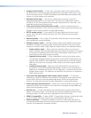
Front Panel Features
1
MODE
2
SINGLE
1
SEPARATE
2
COMBINE DVI/HDMI
1 21 2 3
MUTE
MPS 409
DIGITAL MEDIA PRESENTATION SWITCHER
VIDEO INPUTSHDMI INPUTS
MIC PROGRAM AUDIO
DVI INPUTSVGA/YUV INPUTS
CONFIG
EXEC
MODE
MUTE
a b dc e f g h i j k
ml n o
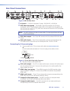
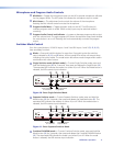
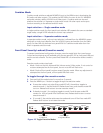
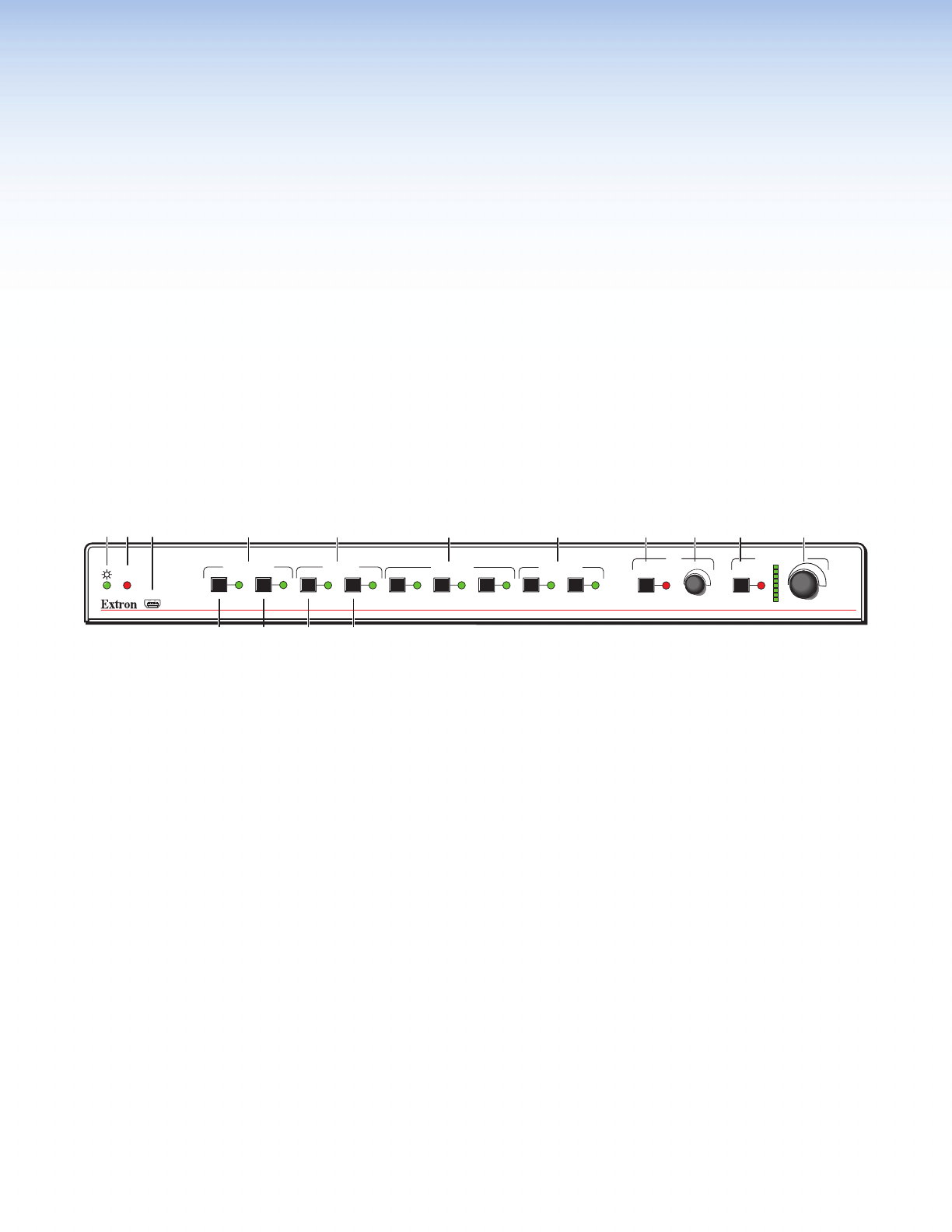
Figure 9. Front Panel Details of the MPS 409 Switcher
a
Power Indicator — This LED lights when power is applied.
b
Executive Mode indicator LED — This red LED lights when Executive mode (front
panel lockout) is active.
c
USB Configuration Port — Mini Type-B- female USB jack used for configuration of the
switcher and flash upgrades of the firmware.
Video/Audio Group Buttons
The controls for the four independent switchers are grouped by input type.
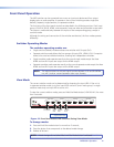
d
VGA/YUV Inputs group — VGA/YUV buttons 1 and 2 select the input for the
VGA/YUV and audio switcher section. The LEDs to the right of each button (when lit)
indicate the selected input.
e
DVI Inputs group — DVI buttons 1 and 2 select the input for the DVI and audio
switcher sections. The LEDs to the right of each button (when lit) indicate which input
has been selected for output.
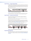
f
HDMI Inputs group — HDMI buttons 1 through 3 select the input for the HDMI and
audio switcher section. The LEDs to the right of each button (when lit) indicate which
input has been selected for output.
g
Composite Inputs group — Video buttons 1 and 2 select the input for the composite
video andaudio switcher section. The LEDs to the right of each button (when lit) indicate
which input has been selected for output.
MPS 409 • Operation 10