


R
ESTRICTED USE ONLY Fargo Electronics, Inc.
Persona C10/M10 ID Card Printer Service Manual (Rev. 4.0)
134
Replacing the Card Feed Switch Assembly (830136)
Refer To Drawing 830131, Item 12.
TTR: NA
In the unlikely event of failure, this cable is not field serviceable. Please contact the FARGO
Technical Support Group at (952) 941-0050 for assistance.
Replacing the LED Board Assembly (830133)
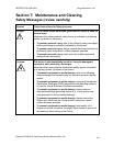
Caution: This device is electrostatic sensitive. It may be damaged if exposed to
static electrical discharges. (Discharges may be generated by various means, such as
walking on a carpeted floor.) Be sure to observe all established Electro-Static Discharge
(ESD) procedures while handling cables in or near the Circuit Board and Printhead
Assemblies. Always wear an appropriate personal grounding device, such as a wrist strap
with integral resistor, connected to an ESD ground to avoid potential damage. At a minimum,
make positive contact with the bare metal chassis of the printer with the hand before
proceeding with the procedure.
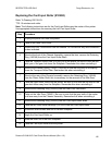
Sub-assembly of 830126, Item 13.
Refer To Drawing 830118-XX.
TTR: 15 minutes
Step Procedure
1 Unplug the power cord from the printer.
2 Take off the Rear Pivot Cover.
3 Detach the Print Circuit Board from the chassis. Do not remove any wire
connectors unless indicated.
4 Remove the Screw (130971) that holds the Lower Ribbon Sensor Assembly to
the Rear Side Plate. Refer to Drawing 830126.
5 Disconnect the cable connector from J12, pins 1and 2 on the Print Circuit
Board.
6 Remove the LED Board Assembly from the Bottom Sensor Bracket and the
printer. See Drawing 830133 for specifications.