


CONNECTIONS
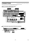
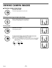
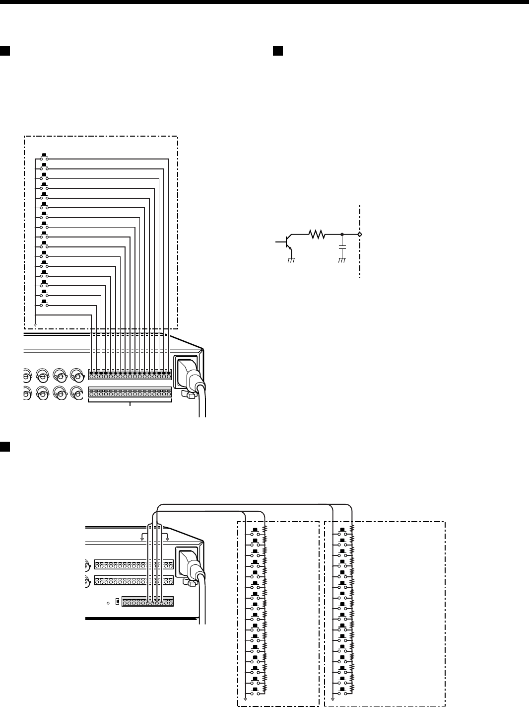
External alarm sensor setup
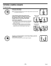
In order to make an external alarm sensor operate, an external
switch must be connected to an ALARM IN connector. When an
intruder activates the external switch (such as by opening a
door), an alarm signal is received and an alarm can be made to
sound.
The MPX-CD93 model uses the connectors marked *.
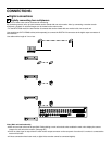
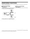
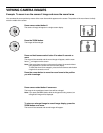
Using as a monitor board during a
motion sensor alarm
When the motion sensor built into the multiplexer responds to an
alarm, it outputs an alarm signal to the SENSOR ALARM OUT
connector. If a switching circuit such as a warning lamp is
connected to this connector, the warning lamp will illuminate
when there is a response from the motion sensor. If the warning
lamp is fixed somewhere in the layout diagram for an area such
as a factory, the location of the camera can be ascertained in an
instant during an emergency. The connector is always open.
The pin corresponding to the number of the camera that
generates a sensor response switches to Low.
*
*
*
*
*
*
*
*
*
Connect an external switch
to an ALARM IN connector
SENSOR ALARM OUT connector
Rated values for each connector (at 25˚C)
• Max. current
• Max. voltage
• Max. power
1K
25mA
25V
40mW
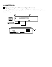
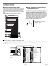
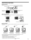
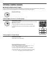
Connecting a remote control circuit
If a remote control circuit is constructed as shown in the illustration and connected to the remote control input (R1 and R2) terminals of
the CONTROL connector, the multiplexer can be operated by remote control. (Contact LOW input)
The MPX-CD93 model can control up to nine cameras.
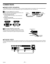
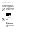
SW 1: Camera1
SW 2: Camera2
SW 3: Camera3
SW 4: Camera4
SW 5: Camera5
SW 6: Camera6
SW 7: Camera7
SW 8: Camera8
SW 9 : Camera9
SW 10 : Camera10
SW 11 : Camera11
SW 12 : Camera12
SW 13 : Camera13
SW 14 : Camera14
SW 15 : Camera15
SW 16 : Camera16
220Ω
220Ω
300Ω
360Ω
470Ω
680Ω
820Ω
1.2kΩ
1.8kΩ
2.2kΩ
3.3kΩ
4.7kΩ
7.5kΩ
13kΩ
27kΩ
68kΩ
SW 17: Menu selection
SW 18: Video playback
SW 19: Live image
SW 20: Multi display
SW 21: Plus display
SW 22: Auto camera switching
SW 23: Electronic zoom
SW 24: Still image
SW 25: Spot monitor
SW 26: 4-screen display
SW 27: Next
SW 28: Previous
SW 29: +
SW 30: –
SW 31: 3
SW 32: 2
220Ω
220Ω
300Ω
360Ω
470Ω
680Ω
820Ω
1.2kΩ
1.8kΩ
2.2kΩ
3.3kΩ
4.7kΩ
7.5kΩ
13kΩ
27k
68kΩ
SW: Switch
R1 R2
The remote control cable should
be no more than 5 m long.
Note:
– 12 –
English