


INTERFACE SPECIFICATIONS
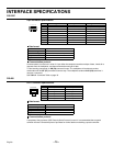
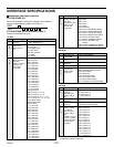
Multiplexer data status command
STATUS SENSE (D7)
When this command is sent by the computer, the multiplexer
returns a 5-byte operating status code (Table 1).
STATUS SENSE (D7) bit allocation (Table 1)
The 4th and 5th bytes are spare.
1st byte
Bit Bit details
7 Indicates LIVE
and VCR
0: Live image mode
1: VCR playback mode
6 Indicates the
main monitor
display using 3
bits
000: Single-screen
5 001: 4-screen
4 010: Multiple-screen
011: Plus screen
100: Menu selection
101: Series
111: Standby
3 Indicates the
display channels
and menu
numbers for each
display on the
main monitor
using 4 bits
(During single-screen)
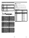
2 0000: Channel 1
1 0001: Channel 2
0 0010: Channel 3
0011: Channel 4
0100: Channel 5
0101: Channel 6
0110: Channel 7
0111: Channel 8
1000: Channel 9
1001: Channel 10*
1010: Channel 11*
1011: Channel 12*
1100: Channel 13*
1101: Channel 14*
1110: Channel 15*
1111: Channel 16*
(During 4-screen)
0000: 4-screen (1, 2, 3, 4)
0001: 4-screen (5, 6, 7, 8)
0010: 4-screen (9, 10*, 11*, 12*)
0011: 4-screen (13*, 14*, 15*, 16*)
(For multiple-screen)
0000: Single-screen
1000: 9-screen
1111: 16-screen*
(For plus screen)
0000: Channel 1
0001: Channel 2
0010: Channel 3
0011: Channel 4
0100: Channel 5
0101: Channel 6
0110: Channel 7
0111: Channel 8
1000: Channel 9
1001: Channel 10*
1010: Channel 11*
1011: Channel 12*
1100: Channel 13*
1101: Channel 14*
1110: Channel 15*
1111: Channel 16*
Bit Bit details
3 Indicates the
display channels
and menu
numbers for each
display on the
main monitor
using 4 bits
(For serial connection)
2 0000: MAIN
1 0001: SUB 1
0 0010: SUB 2
0011: SUB 3
(Menu selection)
0001: Menu 1 MAIN MENU settings
0010: Menu 2 LANGUAGE settings
0011: Menu 3 CLOCK SET settings
0100: Menu 4 DISPLAY SET settings
0101: Menu 5 VCR SET settings
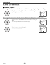
0110: Menu 6 ALARM SET settings
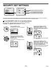
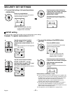
0111: Menu 7 SECURITY SET
settings
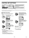
1000: Menu 8 CONTROL SET settings
1001: Menu 9 ALARM DATA settings
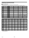
2nd byte
Bit Bit details
7 Indicates EXIT
and ALARM
1: EXIT & ALARM ON
6 Indicates VIDEO
LOSS
1: VIDEO LOSS ON
5 Indicates
SENSOR
1: SENSOR ON
4 Spare 0
3 Indicates the
main monitor
display status
using 4 bits
0000: Normal display
2 0001: Automatic switching display
1 0010: Zoom display
0 0011: Still image
0100: Zoomed still image
0101: Still image zoomed
0110: Zoom position setting
0111: Still image zoom position setting
3rd byte
Bit Bit details
7 Indicates the
currently-
operating spot
monitor using 2
bits
00: Spot monitor 1
6 01: Spot monitor 2
10: Spot monitor 3
11: Spot monitor 4
5 Spot monitor
operation
1: Spot monitor operating
4 Spot monitor
operation
0: Single-screen
1: Automatic switching display
3 Indicates the
camera number
for currently-
operating spot
monitor using 4
bits
Indicates the spot
monitor 1 camera
number when the
main monitor is
operating
0000: Channel 1
2 0001: Channel 2
1 0010: Channel 3
0 0011: Channel 4
0100: Channel 5
0101: Channel 6
0110: Channel 7
0111: Channel 8
1000: Channel 9
1001: Channel 10*
1010: Channel 11*
1011: Channel 12*
1100: Channel 13*
1101: Channel 14*
1110: Channel 15*
1111: Channel 16*
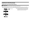
*: Command for MPX-CD163 only
D7
d1 d2 d3 d4 d5
RXD
TXD
English
– 77 –