


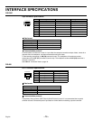

SPECIFICATIONS
Signal format : Based on NTSC color signal standard
Camera signal input synchronization : Asynchronous
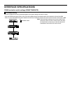
Camera video input connectors : VS/VBS, 1.0 Vp-p/75 Ω, BNC connector x 16 Control signal superimposed when camera operating
(MPX-CD93: BNC connector x9)
Camera video output connectors : Throughput of each input, 1.0 Vp-p/75 Ω, BNC connector x 16 (MPX-CD93: BNC connector x9)
VCR input connector
•
••
•
Composite input : VS/VBS, 1.0 Vp-p/75 Ω, BNC connector x 1
•
••
•
S-Video input connector : Separate YC signals, DIN connector (S terminal) x 1
Y signal: 1.0 Vp-p/75 Ω, unbalanced, synchronous; C signal: 0.286 Vp-p/75 Ω, unbalanced
•
••
•
Digital input connector : RJ-45 x 1
VCR output connector
•
••
•
Composite output : VS/VBS, 1.0 Vp-p/75 Ω, BNC connector x 1
•
••
•
S-Video output connector : Separate YC signals, DIN connector (S terminal) x 1
Y signal: 1.0 Vp-p/75 Ω, unbalanced, synchronous; C signal: 0.286 Vp-p/75 Ω, unbalanced
•
••
•
Digital input connector : RJ-45 x 1
Main monitor output connector
(MAIN MONITOR) : VS/VBS, 1.0 Vp-p/75 Ω, BNC connector x 1
Camera live image or VCR playback image output: single-screen, automatic switching image,
multiple-screen
•
••
•
S-Video output connector : Separate YC signals, DIN connector (S terminal) x 1
Y signal: 1.0 Vp-p/75 Ω, unbalanced, synchronous; C signal: 0.286 Vp-p/75 Ω, unbalanced
Spot monitor output connectors
(SPOT MONITOR 1 - 4) : VS/VBS, 1.0 Vp-p/75 Ω, BNC connector x 4
Camera live image: single-screen (Same image as main monitor selectable using menu/SPOT MONITOR
1 only)
Control connector
•
••
•
Remote control input (R1, R2) : 2-wire type with resistance-based identification system
•
••
•
Alarm output (AL) : 5 V DC, 5.7 kΩ (Low output)
•
••
•
Switch input (SW) : Low input, for input signal from SW OUT of timelapse VCR/real time VCR (as per this manufacturer
specifications)
Alarm input connectors : No voltage, make-contact switch input x 16 (Low input) (MPX-CD93: BNC connector x9)
Sensor alarm output connector : Alarm output x 16 (low output, normally open) (MPX-CD93: BNC connector x9)
RS-485 control connector : RJ-11 type: 2 connectors (A/B), Push-lock type: 3 connectors (A, B, Ground)
RS-232C connector :9-pin D-SUB
Automatic screen switching timing : Available in single-screen and quad mode, with interval selectable from 1 – 30 sec.
Monitor on-screen display : Title (up to 10 characters), date, time selectable
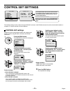
Menu settings