


Maintenance and Specifications
Specifications
8
8-13
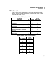
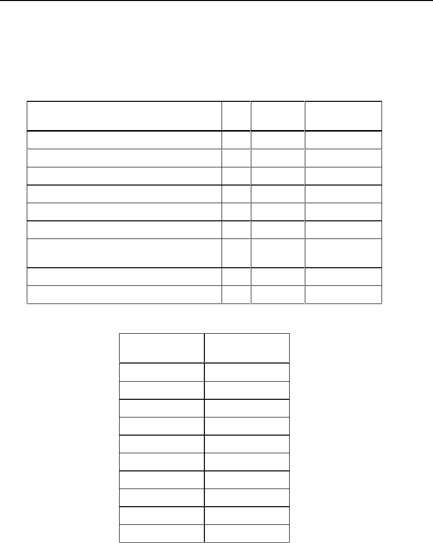
PC Interface Cable
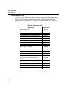
Table 8-7 shows the pin connections for the PC interface cable provided with the
test tool. Table 8-8 shows the pin connections for the 9-to 25-pin adapter available
from Fluke (part number 929187).
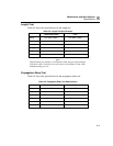
Table 8-7. PC Interface Cable Connections
Test Tool End
DB9S (female) Pin Direction
PC End
DB9S (female)
Data Carrier Detect 1 <----- 4
Receive Data 2 <----- 3
Transmit Data 3 -----> 2
Data Terminal Ready (always true) 4 -----> 1
Signal Ground 5 <----> 5
Not connected 6 6
Request To Send (used only with hardware
flow control)
7 -----> 8
Clear To Send 8 <----- 7
Not connected 9 9
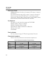
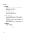
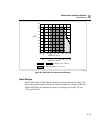
Table 8-8. 9-to 25-pin Adapter (available from Fluke)
9-pin Connector
25-pin
Connector
32
23
74
85
66
57
18
420
922
Shell Shell