DSP-100/2000
Users Manual
4-6
The TDX Analyzer
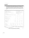
The TDX (Time Domain Crosstalk) analyzer displays the locations where
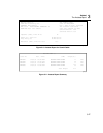
crosstalk is occurring on the cable. You can view the test results in a list or plot
format. The list format shows the largest crosstalk value detected on the cable.
The plot shows all of the crosstalk detected.
The crosstalk values displayed are adjusted to compensate for cable attenuation.
The values represent the approximate levels of crosstalk as they appear at the
sources of the crosstalk. A level over 50 represents a crosstalk magnitude that
exceeds the limit specified by the selected test standard.
The TDX analyzer results are not intended for use in determining if a cable meets
specifications; the results are intended to help you locate the sources of crosstalk
on a cable. To determine if a cable meets specifications for crosstalk, run the
NEXT test.
Running the TDX Analyzer
Note
You can run the TDX analyzer with or without a remote. If you run
the analyzer without a remote, the results may be unreliable.
To run the TDX analyzer, proceed as follows:
1. Turn off any PCs connected to the link you are testing.
2. If you are using a DSP-100 main unit as a remote, turn the remote unit’s
rotary switch to SMART REMOTE. If you are using a smart remote unit, turn
its rotary switch to ON.
3. If you are testing with a remote, connect the remote to the far end of the cable
link.
4. Turn the rotary switch on the main unit to SINGLE TEST.
5. Verify that the test standard and cable type displayed are correct.
6. On Model DSP-100, remove any cable connected to the test tool’s BNC
connector.
7. Connect the test tool to the near end of the cable link. On Model DSP-2000,
connect to the CABLE TEST jack.
8. Use D to highlight TDX Analyzer.
9. Press E to run the TDX analyzer.


