


Installing and Maintaining the E1200i System 17
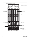
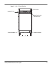
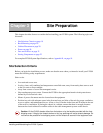
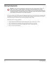
Figure 4 E1200i DC Chassis Rear View
Table 2 E1200i Hardware Component Operating Requirements Summary
Component Minimum Maximum Field-Replaceable
Backplane (factory installed) 1 1 N
Air filter (factory installed) 1 1 Y
Fan trays 2 2 Y
RPMs 1 2 Y
Line cards 1 14 Y
SFMs 8 9 Y
AC Power Supply 2 6 Y
DC Power Supply 1 2 Y
Cable management system 0 1 Y
Cable management system cover 0 1 Y
Self-closing Door
Installed Fan Tray
Empty Fan Tray with
Locking screw
Ground Connection
Ground Connection