


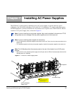


36 Installing AC Power Supplies
Secure your chassis ground first and then install each power supply.
Securing the Chassis Ground
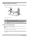
Installing Power Supplies
Step Task
1. Locate the chassis ground connector nuts on the chassis rear (see Figure 2 on page 15).
2. Install the grounding cables to the ground nuts. The grounding cable must comply with your local electrical
codes in size and color (typically the color is green or green with yellow stripe).
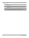
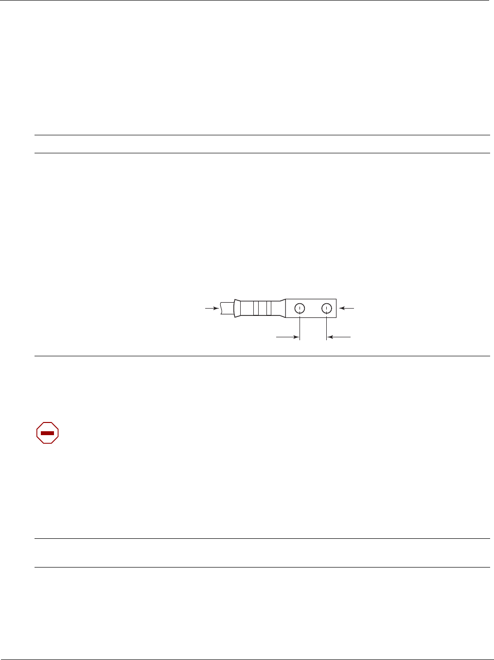
Note: Grounding cables must be terminated only with a UL-listed 2-hole lug with 1/4-inch holes on
3/4-inch spacing (see Figure 12).
a Use ANSI UNC 1/4-20 x 1/2 bolt.
b Tighten the bolt (torque should not exceed 25inch/lbs).
c Connect the opposite end of the grounding cable to the nearest appropriate facility grounding post.
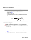
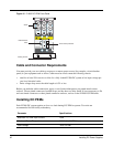
Figure 12 Cable Connector Required for E1200i AC
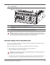
Caution: An E1200i AC power supply still has power after extraction, and has completely
powered off when the fans have stopped rotating. When replacing a power supply, to avoid arcing
and discoloration of the supply and the chassis pins, please wait for the fans to stop rotating before
reinserting the supply
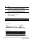
Step Task
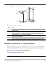
1. Make sure that the On/Standby switch, located on the left side of plug AC-0, is in the Standby (up) position
(Figure 11).
2. Loosen the cord retainers locking screws (if needed) and tilt the AC-cord retainer up approximately 15
o
and gently slide the cover away from the chassis.
0.750"
H
igh-strand-count
conductor
diameter
2 Holes
All measurements in inches.
FN00011A
0.267