


Installing and Maintaining the E1200i System 53
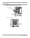
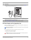
Installing a Second RPM
Install a second RPM either before the system is powered on or after the Primary RPM is up and stable.
After the second RPM is installed, wait several seconds until the connection between the two RPMs is
established before configuring any commands. Below is an example of the messages that should appear:
%POLLMGR-2-ALT_RPM_STATE: Alternate RPM is present
%IRC-6-IRC_COMMUP: Link to peer RPM is up
%RAM-6-RAM_TASK: RPM1 is in Standby State.
Once the link between the two RPMs is established, copy the running configuration to the startup
configuration.
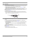
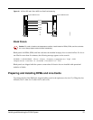
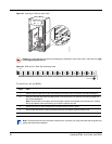
RPM Label and LEDs
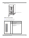
Table 6 describes the RPM LED states and the RPM front panel.
Note: If your system contains two RPMs, both RPMs must contain the same software image.
Table 6 RPM LEDs
Section Label Description
Management 10/100
Ethernet
L: Green: link is up
A: Green: activity on port
Alarms Major Red: a critical condition exists, such as a severe over temperature condition, a fan
tray failure, an overcurrent condition in a power supply, or an out-of-tolerance
voltage.
The RPM LEDs are controlled by software which sets the threshold levels for
triggering the different stages of alarms.
Unlit: no major conditions
Minor Amber: a serious condition exists, such as an over temperature condition, a single
fan failure, or a line card failure. The RPM LEDs are controlled by software,
which sets the threshold levels for triggering the different stages of alarms.
Unlit: no minor alarm conditions
ACO/LT Allows you to test the operability of LEDs to verify that they are able to light.
Press the ACO/LT button to temporarily illuminate the LEDs on the RPM.
If you press this button when the alarm status LED is lit, the alarm relay contacts are
reset until the next alarm event.
Flash In Use Green: flash memory card is in the process of a read or write process. Do not
remove the flash card when the In Use LED is lit.
Unlit: not in use