


Installing and Maintaining the E1200i System 65
This chapter provides instructions for removing and replacing E1200i AC and DC components. It covers
the following topics:
• Removing and Replacing Fan Trays
• Removing and Replacing AC Power Supplies
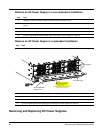
• Removing and Replacing DC Power Supplies
• Removing and Replacing RPMs, Line Cards, or SFMs
• Removing and Replacing the Air Filter
When a component fails, the E1200i system triggers major or minor alarm LEDs (located on the RPM),
sends events to the SNMP trap and show alarms table, disables or changes component Status LEDs or
triggers an audible alarm. Refer to Appendix C, on page 87 for more information on alarms.
Removing and Replacing Fan Trays
In the event of a fan tray failure, signified by an amber LED, an SNMP trap, or major alarm event, the
entire fan tray must be replaced. If one or more fans within a fan tray fail, the system generates a minor
alarm and an SNMP trap.
The fan trays are hot-swappable.
To remove and replace the fan tray, you must have access to the rear of the chassis and be able to pull the
fan tray completely out of the slot (at least 20 inches).
To remove and replace a fan tray:
Chapter 12 Removing and Replacing
Components
Step Task
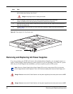
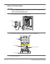
1. Prior to removing a fan tray, turn the screw latch counter-clockwise (with a flathead screwdriver) one
quarter of a turn to unlock the fan tray. (Figure 26).