


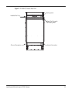
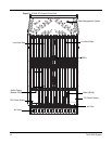
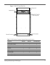

18 The E1200i System
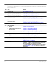
To install the E1200i system, Force10 Networks recommends that you perform the installation procedures
in the following order:
Step Task Section
1. Prepare the site Site Preparation on page 19
2. Unpack the AC chassis and components
or
Unpack the DC chassis and components
Unpacking the E1200i AC System on page 23
Unpacking the E1200i DC System on page 27
3. Mount the AC chassis
or
Mount the DC chassis
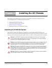
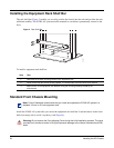
Standard Front Chassis Mounting on page 24
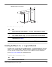
Installing the Chassis into an Equipment Cabinet on page 25
Standard Front Chassis Mounting on page 28
Installing the Chassis into an Equipment Cabinet on page 29
4. Install the cable management system See the instructions that come with the cable management system.
5. Install components:
• Fan trays
• Power Supplies (including power and
grounding cables)
Installing Fan Trays on page 31
Installing AC Power Supplies on page 35
Installing DC Power Supplies on page 41
6. Verify power supply and fan tray operability AC Power Supply and Fan Operability Test on page 37
DC Power Supply and Fan Operability Test on page 47
7. Install card components:
• RPM(s) and line cards
•SFMs
Installing Line Cards and RPMs on page 50
Installing Switch Fabric Modules (SFMs) on page 54
8. Connect network cable RPM Ports and Cables on page 57
9. Supply power to the chassis Supplying Power - AC on page 62
Supplying Power - DC on page 62
10. Initial boot The initial boot operation automatically brings up the system to the
runtime CLI. To interrupt the automatic boot process, issue a break
key sequence (Ctrl^) if you experience boot problems.
The console monitor will display the default BOOT_USER # prompt.
Refer to Appendix B, on page 79 for instructions to continue the
boot process.