57
2 Connector Specifications
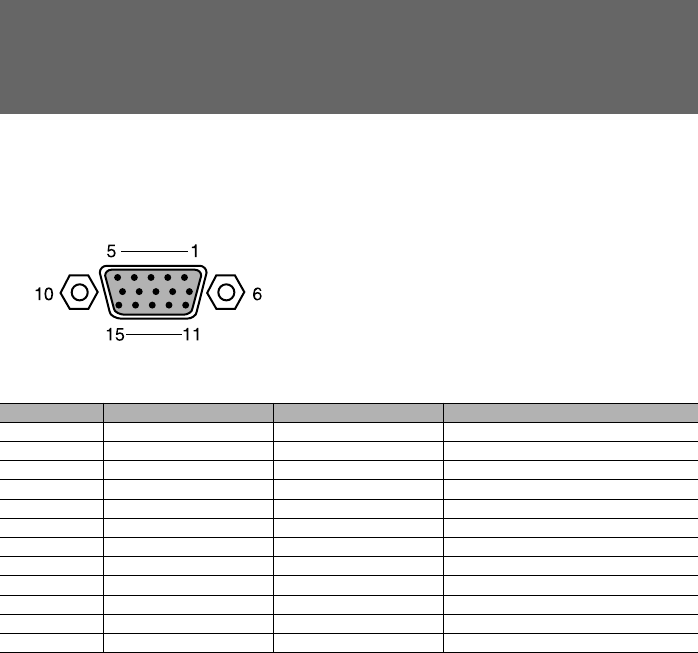
The following table provides the pin assignment and signal names.
● CRT connector
Pin number Signal name Direction Description
1 RED Output Red (R) signal output
2 GREEN Output Green (G) signal output
3 BLUE Output Blue (B) signal output
4 NC – Not connected
5 - 8 GND – Ground
9 +5V – +5V
10 GND – Ground
11 NC – Not connected
12 SDA Input and output Data
13 HSYNC Output Horizontal synchronization signal
14 VSYNC Output Vertical synchronization signal
15 SCL Input and output Data clock
CHAPTER 5 Bennett (53-60) 12/6/02, 10:31 AM57


