


Contents
xii C141-E167
Illustrations
Figures
1.1 6-Byte CDB Basic Format ............................................................................................................ 1-1
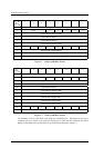
1.2 10-Byte CDB Basic Format .......................................................................................................... 1-2
1.3 12-Byte CDB Basic Format .......................................................................................................... 1-2
1.4 Status Byte .................................................................................................................................... 1-6
1.5 Data space configuration............................................................................................................. 1-31
2.1 Data buffer configuration (in the case of 8 cache segments)........................................................ 2-2
2.2 Example of data buffer operation during read .............................................................................. 2-3
2.3 Example of data buffer operation during write............................................................................. 2-4
2.4 Parameters for controlling reconnection timing............................................................................ 2-5
2.5 Cache control parameters.............................................................................................................. 2-9
3.1 Standard INQUIRY data............................................................................................................... 3-4
3.2 Command support data ................................................................................................................. 3-9
3.3 VPD information: VPD identifier list ........................................................................................3-11
3.4 VPD information: device serial No............................................................................................ 3-11
3.5 VPD information: operation mode.............................................................................................3-12
3.6 READ CAPACITY data ............................................................................................................. 3-14
3.7 MODE SELECT parameter structure ......................................................................................... 3-21
3.8 MODE SELECT command (Group 0) parameter configuration ................................................ 3-23
3.9 MODE SELECT EXTENDED command (Group 2) parameter configuration.......................... 3-28
3.10 MODE SENSE command (Group 0) parameter configuration................................................... 3-31
3.11 MODE SENSE EXTENDED command (Group 2) parameter configuration............................. 3-35
3.12 SET LIMITS command: Specifying the range where access is permitted................................. 3-73
3.13 FORMAT UNIT command parameter list configuration............................................................ 3-78
3.14 Defect descriptor: Byte distance from index format.................................................................. 3-80
3.15 Defect descriptor: physical sector address format...................................................................... 3-81
3.16 REASSIGN BLOCK command: defect data list configuration ................................................. 3-86
3.17 READ DEFECT DATA command: Defect data configuration ................................................. 3-89
3.18 SEND DIAGNOSTIC command: parameter list configuration................................................. 3-95
3.19 SEND DIAGNOSTIC parameters: page code list ..................................................................... 3-96
3.20 SEND DIAGNOSTIC parameters: logical/physical address conversion................................... 3-96
3.21 RECEIVE DIAGNOSTIC RESULTS command: Response data configuration ....................... 3-99
3.22 RECEIVE DIAGNOSTIC RESULTS response data: page code list....................................... 3-100
3.23 RECEIVE DIAGNOSTIC RESULTS response data: logical/physical address conversion .... 3-101
3.24 WRITE BUFFER command: buffer data (Mode =000,001).................................................... 3-103
3.25 READ BUFFER command: buffer data (Mode =0000,0001) ................................................. 3-108
3.26 READ BUFFER command: buffer descriptor ......................................................................... 3-109
3.27 READ BUFFER command: Echo buffer descriptor................................................................ 3-110