


3.4 Maintenance, Diagnostic Commands
C141-E167
3 - 107
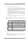
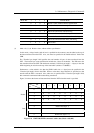
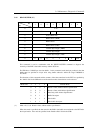
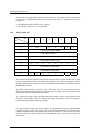
3.4.4 READ BUFFER (3C)
Bit
Byte
76543210
0X‘3C’
1 LUN 0 Mode
2 X‘00’ (Buffer ID)
3 Buffer Offset (MSB)
4 Buffer Offset
5 Buffer Offset (LSB)
6 Transfer Byte Length (MSB)
7 Transfer Byte Length
8 Transfer Byte Length (LSB)
9 0000000Link
This command is used in combination with the WRITE BUFFER command to diagnose the
normalcy of the IDD’s data buffer memory and the SCSI bus.
The IDD have a 7680 K byte size data buffer.. In this command, each data byte position in the data
buffer must be specified in 4-byte units using buffer addresses within the range X'000000' to
X'77FFFF'.
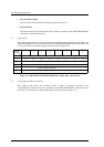
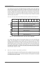
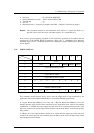
The functions of this command and the contents of the data transferred to the INIT are specified by
the “Mode” field in the CDB and one of the transfer modes shown below can be selected.
“Mode” Bit 3 2 1 0 Transfer Mode
0 0 0 0 Header + Data, without Address Specification
0 0 0 1 Header + Data, with Address Specification
0 0 1 0 Data Only, with Address Specification
0011Buffer Descriptor
1 0 1 0 Echo buffer
1 0 1 1 Echo buffer descriptor
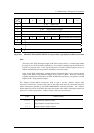
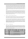
(1) Mode = 0, 0, 0, 0: Header + data, without address specification
When this mode is specified, the data stored in the IDD’s data buffer are transferred to the INIT after
the 4-byte header. Zero must be specified in the “Buffer offset” field in the CDB.