


3.4 Maintenance, Diagnostic Commands
C141-E167
3 - 103
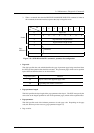
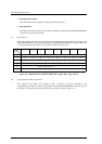
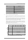
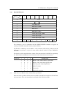
“Mode Bit” 3 2 1 0 Transfer Mode
0 0 0 0 Header + Data, without Address Specification
0 0 0 1 Header + Data, with Address Specification
0 0 1 0 Data Only, with Address Specification
0 1 0 0 Microcode Download, without Saving
0 1 0 1 Microcode Download, with Saving
0 1 1 0 Microcode Download with offset, without Saving
0 1 1 1 Microcode Download with offset, and Saving
1 0 1 0 Echo buffer
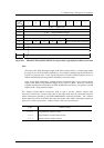
(1) Mode = 0, 0, 0, 0: Header + data, without address specification
In this mode, a 4-byte header (with all zero’s specified for the contents) must be added to the top of
the data transferred from the INIT. Also, zero must be specified in the “Buffer address” field of the
CDB.
The “Transfer byte length” field specifies the total number of bytes of data transferred form the
INIT. The transfer byte count specification includes the 4 bytes of the header. The IDD stores the
data transferred from the INIT with the header omitted (“Transfer byte length” – 4 bytes) in the data
buffer beginning in order from the top of the data buffer (Address: X ‘000000’).
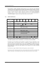
Furthermore, a value which is less than the [IDD’s buffer size + 4 bytes] must be specified in the
“Transfer byte length” field in the CDB. When a value that is larger than this is specified, no data
transfer with the INIT is executed. Also, when zero is specified in the “Transfer byte length” field,
this command is terminated without data being transferred.
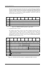
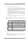
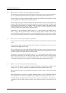
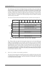
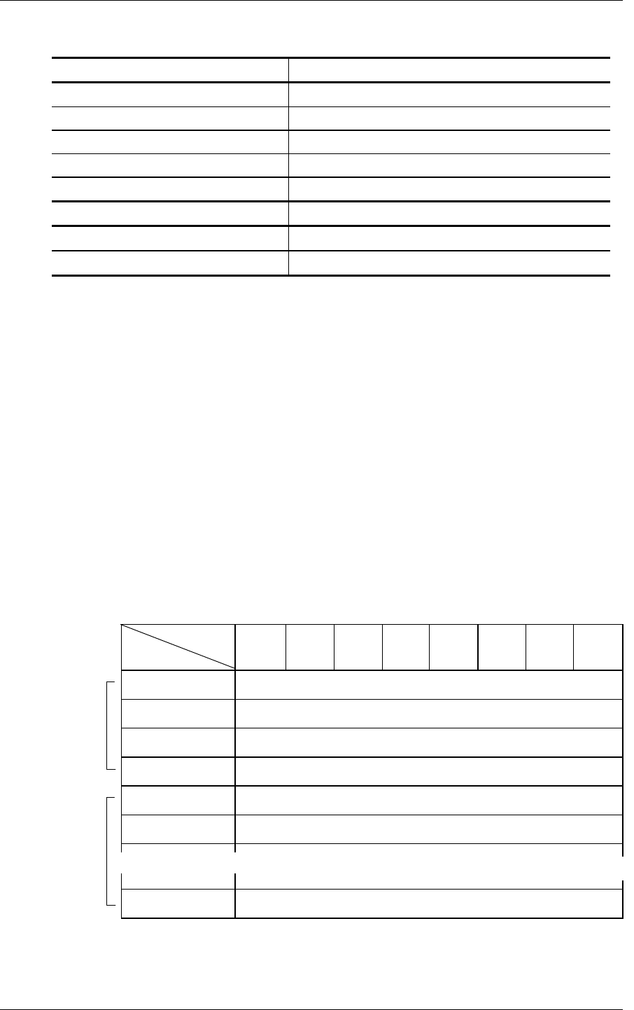
Figure 3.24 shows the format of data transferred from the INIT when this mode is specified.
Bit
Byte
76543210
000000000
1 00000000
2 00000000
3 00000000
4 Buffer Data (Byte 0)
5 Buffer Data (Byte 1)
n Buffer Data (Byte n–4)
Figure 3.24 WRITE BUFFER command: buffer data (Mode = 000, 001)
~
~
~
~
~
~
Header
Data