


4.1 Mode Parameters
C141-E167 4 - 31
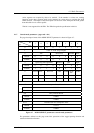
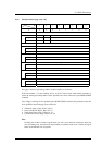
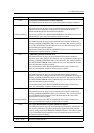
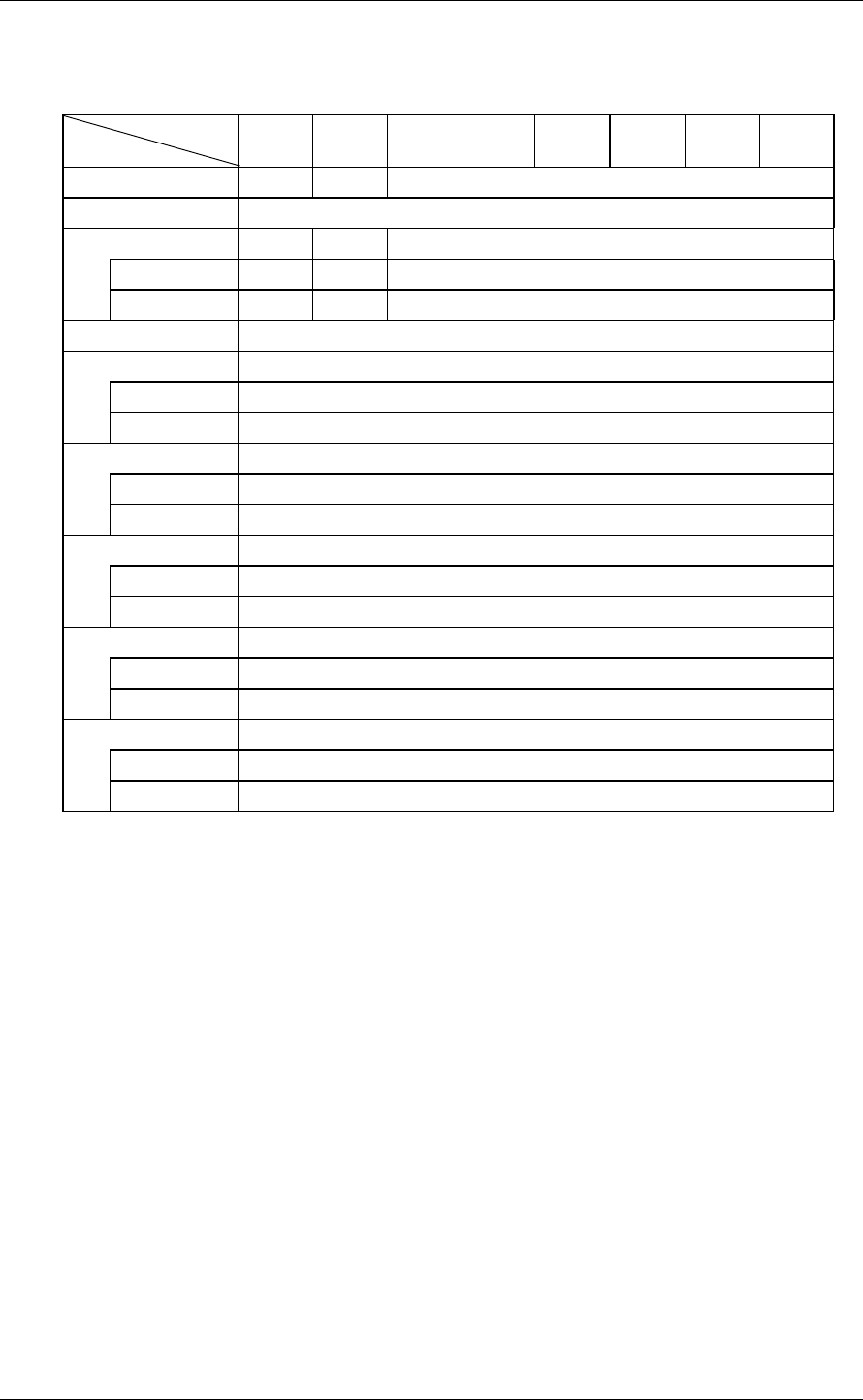
4.1.8 Notch parameter (page code = 0C)
Bit
Byte
76543210
0 00001100
1 X‘16’ (Page Length)
2 ND LPN X‘00’ (Reserved)
Default 00000000
Variable01000000
3 X‘00’ (Reserved)
4-5 Maximum number of notches
Default X‘00xx’
Variable X‘0000’
6-7 Active Notch
Default X‘0000’
Variable X‘FFFF’
8-11 Starting Boundary
Default X‘00000000’
Variable X‘00000000’
12-15 Ending Boundary
Default X‘xxxxxxxx’
Variable X‘00000000’
16-23 Page Notch
Default X‘0000000000000008’
Variable X‘0000000000000000’
This page is used to report the top address and final address of each zone.
If the zone number + 1 of the notching zone is set in the "Active notch" field and this parameter is
issued, the starting and ending address of the specified zone can be referred to by the MODE SENSE
command.
Also, if Page 3 and Page 3F are specified by the MODE SENSE command, the parameters below the
zone specified in the notch page can be referred to.
• Track/zone (Page 3, Byte 02, 03) (Note)
• Sector count/track (Page 3, Bytes 10, 11)
• Track Skew Factor (Page 3, Bytes 16, 17)
• Cylinder Skew Factor (Page 3, Bytes 18, 19)
Note:
Normally, the number of tracks (logical heads) per cell is set in the track count/zone, but in the
case of notching only, the total track count (number of cylinders in the zone x number of logical
heads) of the affected zone is reported.