


Command Specifications
3 - 12 C141-E167
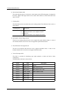
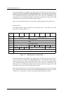
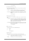
The values indicated in the "Qualifier" and "Device Type Code" fields in byte 0 are the same as
those in the previously mentioned standard INQUIRY data. The "Page code" field in byte 1
indicates the page code (X '80') of this VPD information itself. Also, the "Page length" field in
byte 3 indicates the length (byte length) after byte 4. This value has no relationship to the
specification in the "Transfer Byte Length" in the CDB, but indicates the length of this VPD
information and is always X '0C' (Total data length = 16 bytes).
Bytes 4 to 15 indicate the IDD's device serial number in right-justified decimal (ASCII code).
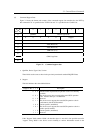
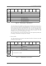
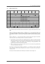
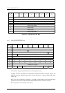
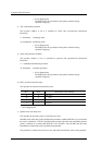
c. Operation mode
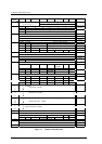
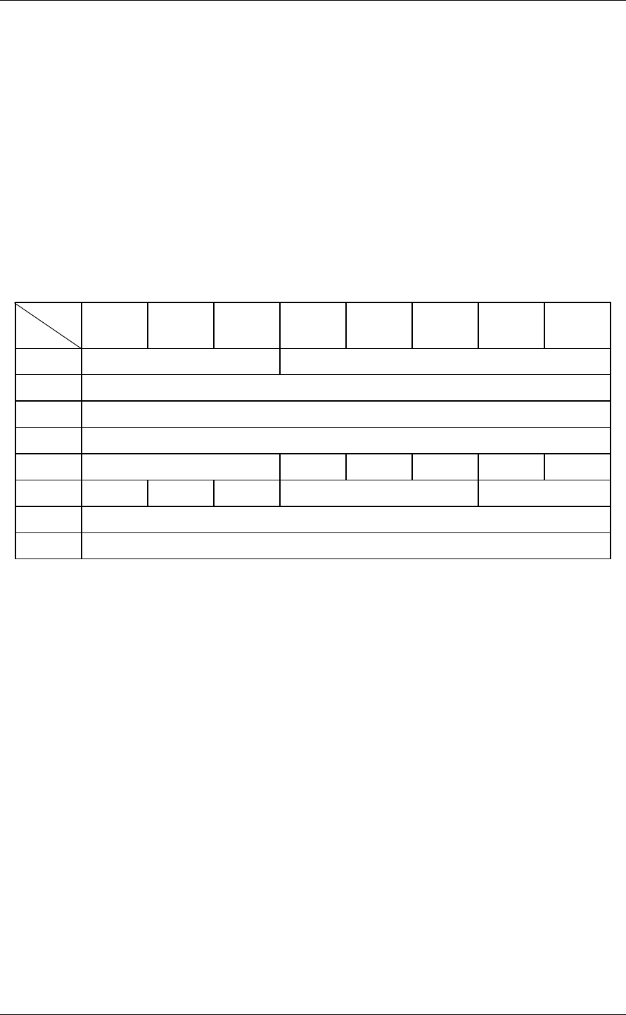
This VPD information reports the IDD's current operation mode. The format of this VPD
information is shown in Figure 3.5.
Bit
Byte
76543210
0 Qualifier Device Type Code
1 X‘C0’ (Page Code)
2 X‘00’
3 X‘04’ (Page Length)
4 0 0 0 WDTR UNTAIN SDTR RSRTY 0
5 PHSCRC AGD ACE 0 0 0 RTD
6 X‘xx’ (Spindle Motor Start Delay Timing)
7 X‘00’ (Reserved)
Figure 3.5 VPD information: operation mode
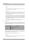
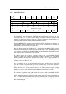
The values indicated in the "Qualifier" and "Device Type Code" fields in byte 0 are the same as
those in the previously mentioned standard INQUIRY data. The "Page code" field in byte 1
indicates the page code (X 'C0') of this VPD information itself. Also, the "Page length" field in
byte 3 indicates the length (byte length) after byte 4. This value has no relationship to the
specification in the "Transfer Byte Length" in the CDB, but indicates the length of this VPD
information and is always X '04' (Total data length = 8 bytes).
Byte 4 and subsequent bytes list all the VPD information page modes currently set in the IDD.
This operation mode setting is performed by the CHANGE DEFINITION command, described
in Section 3.1.4, and Section 3.1.4 shows concerning a detailed definition of each bit.