


Command Specifications
3 -
102
C141-E167
The description of address information shown in bytes 6 to 13 is the same as the description
specifications in the D List transferred from the INIT by the FORMAT UNIT command. For details,
see the description of the FORMAT UNIT command (Section 3.3.1). Furthermore, When the logical
block format is used, the address is shown in bytes 6 to 9 and zero is reported in the remaining byte
positions. However, when the address information specified in the “SEND DIAGNOSTIC
command points to a position on the disk media which is not used as physical data blocks, X
‘FFFFFFFF 00000000’ is reported as the logical block address after conversion.
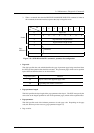
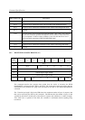
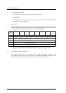
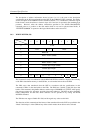
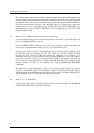
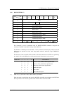
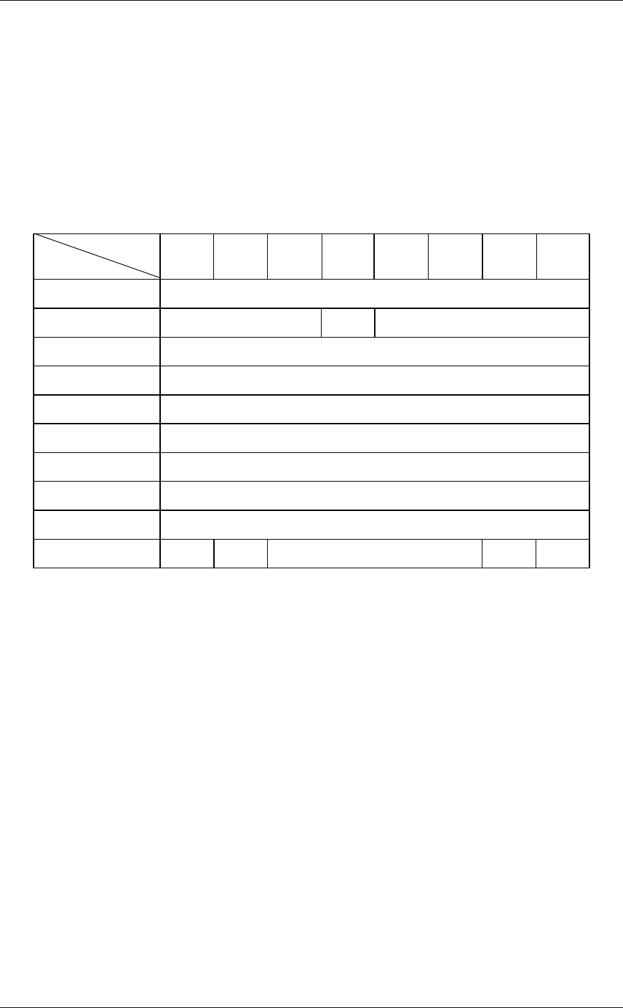
3.4.3 WRITE BUFFER (3B)
Bit
Byte
76543210
0X‘3B’
1 LUN 0 Mode
2 Buffer ID
3 Buffer Address (MSB)
4 Buffer Address
5 Buffer Address (LSB)
6 Transfer Byte Length (MSB)
7 Transfer Byte Length
8 Transfer Byte Length (LSB)
9 0000000Link
This command is used in combination with the READ BUFFER command to diagnose the normality
of the IDD’s data buffer memory or the SCSI bus, or to download microcode to the IDD.
The IDD stores data transferred from the INIT in accordance with the specifications in this
command's CDB to in the data buffer in the IDD. The IDD have 7,680 K (7,864,320) byte data
buffers. This command, using buffer addresses with a range of X'000000' to X'77FFFF', must specify
data storage positions in 1-byte units, and with 4-byte units addresses. The INIT can know the IDD's
buffer configuration and the units which addresses can be specified in by issuing the READ
BUFFER command.
The IDD does not support "Buffer ID" field, and disregards any values to this field.
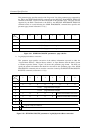
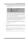
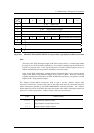
The functions of this command and the format of data transferred from the INIT are specified in the
“Mode” field in byte 1 of the CDB and any of the transfer modes shown below can be selected.